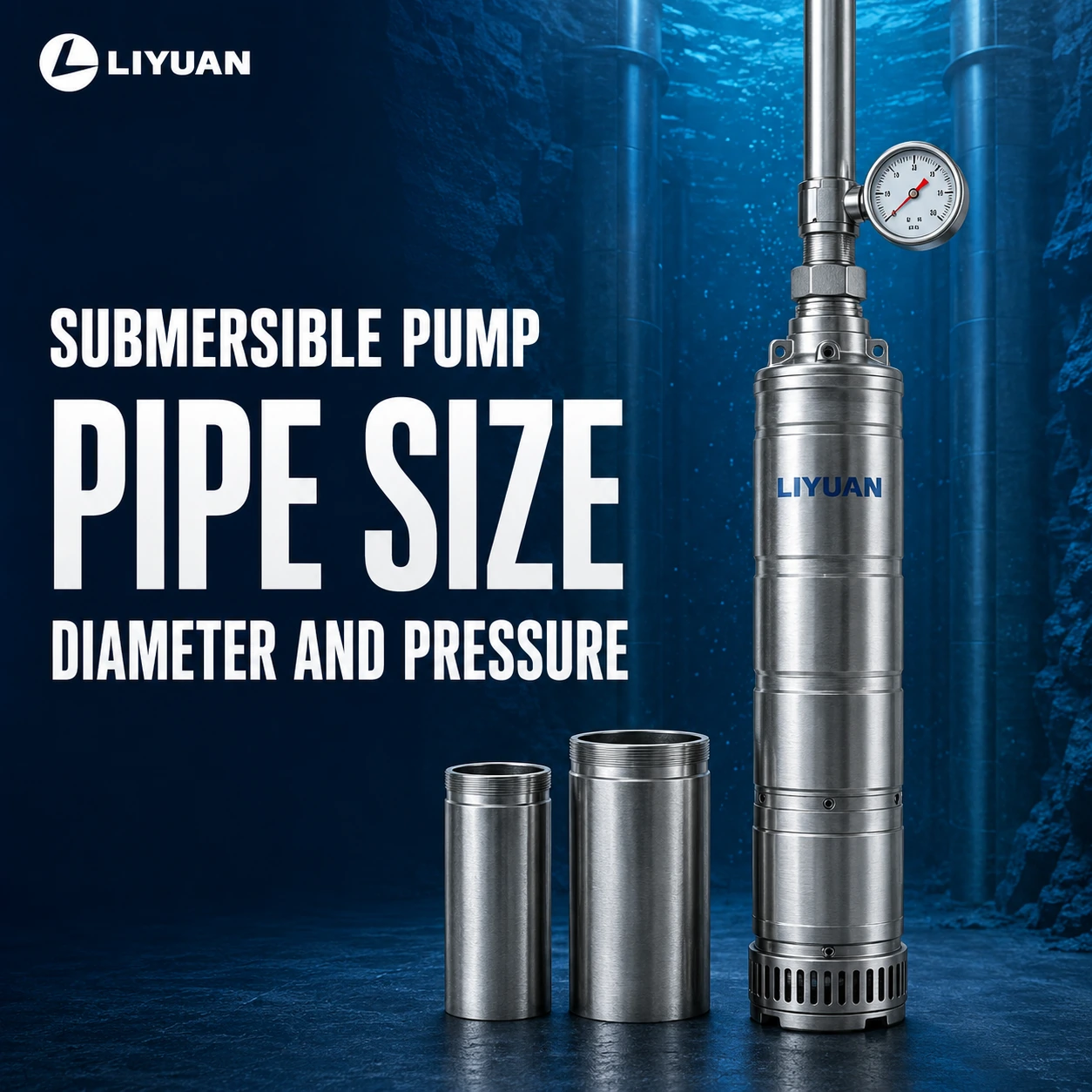
Submersible Pump Pipe Size: How To Choose The Right Diameter And Pressure Rating
The correct submersible pump pipe size is the smallest practical internal diameter that keeps friction loss acceptable at the required flow while also meeting maximum pressure, suspended-load, joint-strength, water-quality, and installation requirements.
Do not select drop pipe only from the pump outlet size or well depth. A pipe can be hydraulically large enough but mechanically unsafe, or structurally strong enough while wasting excessive pump head through friction.
The Four Tests Every Submersible Pump Pipe Must Pass
A reliable pipe selection must pass four separate tests.
| Selection Test | Question The Pipe Must Answer | Main Failure If Ignored |
|---|---|---|
| Hydraulic Diameter | Is friction acceptable at the required flow? | Low flow, low pressure, high energy use |
| Pressure Rating | Can it withstand operating, shut-off, static, and surge pressure? | Leaks, burst pipe, joint failure |
| Suspended Load | Can the pipe and connections support the installed assembly? | Pump loss, separated joints, damaged well |
| Installation Compatibility | Will it fit, remain potable-water compatible, and tolerate the environment? | Difficult installation, corrosion, contamination |
Passing only one or two tests is not enough. The final selection must satisfy all four at the same time.
Why Pump Outlet Size Does Not Automatically Equal Pipe Size
The discharge connection provides a physical connection point. It does not determine the most economical diameter for the full pipe run.
A pump with a 2-inch discharge may need:
- A 2-inch drop pipe for a short, moderate-flow installation
- A larger mainline after the wellhead for a long horizontal run
- A larger drop pipe when friction at the design flow is excessive
- A reducer or transition approved for the selected pump and pipe system
The minimum pipe diameter should not be smaller than the pump manufacturer permits. The economic diameter may be larger than the discharge connection when reduced friction saves pump head and operating energy.
Step 1: Define The Required Flow Before Choosing Pipe Diameter
Pipe size starts with required flow, not motor horsepower.
Required flow may come from:
- Peak residential demand
- The largest irrigation zone
- Livestock tank refill time
- Industrial process demand
- Storage-tank filling time
- Fire-water or municipal design criteria
Use the actual design flow in GPM, liters per second, or cubic meters per hour. Do not use maximum pump flow unless the system will really operate there.
If flow has not been established, calculate it first with the Submersible Pump Flow Rate.
Step 2: Use Actual Internal Diameter, Not Nominal Size
Nominal pipe size is a product designation. It may not equal the actual internal diameter used in friction calculations.
Internal diameter changes with:
- Pipe material
- Schedule
- SDR or SIDR
- Pressure class
- Wall thickness
- Manufacturer tolerances
Two pipes sold under the same nominal size can therefore produce different velocity and friction loss.
RPS Solar Pumps’ Pipe Sizes And Diameters Explanation distinguishes IPS, CTS, SDR, and SIDR dimensions. The correct value for hydraulic calculation is the manufacturer’s published internal diameter.
Step 3: Screen Candidate Sizes By Water Velocity
Velocity is useful for eliminating obviously unsuitable pipe sizes, but it is not a complete selection method.
Use:
Velocity = Flow ÷ Internal Flow Area
For a circular pipe:
Internal Flow Area = π × Internal Diameter² ÷ 4
Excessive velocity can increase:
- Friction loss
- Water hammer
- Noise
- Valve wear
- Check-valve impact
- Energy consumption
Very low velocity can increase pipe cost and may be undesirable in systems that require periodic flushing or sediment transport.
The acceptable range depends on application, pipe material, water quality, surge analysis, and local design rules. Do not use one universal velocity limit for every well system.
Step 4: Calculate Friction Loss For Every Candidate Diameter
Friction loss depends on flow, internal diameter, length, material roughness, and fittings.
For many clean-water calculations, the Hazen-Williams equation in SI units can be written as:
hᶠ = 10.67 × L × Q^1.852 ÷ (C^1.852 × d^4.87)
Where:
- hᶠ = Friction head loss in meters
- L = Pipe length in meters
- Q = Flow in cubic meters per second
- C = Hazen-Williams coefficient
- d = Actual internal diameter in meters
Washington State University provides a Pipeline Pressure-Loss Calculator that uses flow, internal diameter, length, and pipe material. It also treats fittings as additional equivalent pipe length.
For fluids or conditions where Hazen-Williams is unsuitable, use Darcy-Weisbach with an appropriate friction factor.
Submersible Pump Pipe Size Friction Table
The following engineering table compares straight-pipe friction for smooth pipe using a Hazen-Williams coefficient of 150.
Values show approximate meters of head loss per 100 meters of straight pipe.
| Flow | 32 mm ID | 40 mm ID | 50 mm ID | 63 mm ID | 75 mm ID |
| 3 m³/h | 3.76 m | 1.27 m | 0.43 m | 0.14 m | 0.06 m |
| 6 m³/h | 13.58 m | 4.58 m | 1.54 m | 0.50 m | 0.21 m |
| 10 m³/h | 34.97 m | 11.80 m | 3.98 m | 1.29 m | 0.55 m |
| 15 m³/h | 74.10 m | 25.00 m | 8.43 m | 2.74 m | 1.17 m |
| 25 m³/h | 190.84 m | 64.38 m | 21.72 m | 7.05 m | 3.01 m |
This table is not a universal pipe chart. It excludes fittings and applies only to the stated actual internal diameters, length, water flow, and assumed coefficient.
Its purpose is to show why a small change in submersible pump pipe size can cause a large change in required pump head.
Why Pipe Diameter Has Such A Large Effect
In the Hazen-Williams relationship, internal diameter is raised to approximately the 4.87 power.
At 10 m³/h, increasing the assumed internal diameter from 40 mm to 50 mm reduces straight-pipe friction from approximately 11.8 meters to 3.98 meters per 100 meters.
That is a reduction of about 7.82 meters of head for every 100 meters of pipe under the stated assumptions.
For a 300-meter route, the difference becomes approximately 23.5 meters before fitting losses are added.
Choosing a larger pipe may therefore allow:
- A lower-head pump
- Fewer pump stages
- Lower motor power
- Reduced energy consumption
- More pressure at the destination
- Greater tolerance for seasonal water-level changes
Worked Example: Selecting Between 40, 50, And 63 mm Internal Diameter
Assume a farm water system has:
- Required flow: 10 m³/h
- Dynamic water level: 70 meters below ground
- Outlet elevation: 15 meters above the wellhead
- Required outlet pressure: 3 bar
- Drop pipe plus horizontal pipe: 320 meters
- Fitting allowance: 15% of straight-pipe friction
- Smooth-pipe Hazen-Williams coefficient: 150
Convert pressure to head:
Pressure Head = 3 × 10.2 = 30.6 Meters
The non-friction head is:
70 + 15 + 30.6 = 115.6 Meters
Candidate A: 40 mm Internal Diameter
Straight-pipe friction:
11.80 × 3.2 = 37.76 Meters
Including the 15% fitting allowance:
37.76 × 1.15 = 43.42 Meters
Approximate TDH:
115.6 + 43.42 = 159.02 Meters
Candidate B: 50 mm Internal Diameter
Straight-pipe friction:
3.98 × 3.2 = 12.74 Meters
Including the fitting allowance:
12.74 × 1.15 = 14.65 Meters
Approximate TDH:
115.6 + 14.65 = 130.25 Meters
Candidate C: 63 mm Internal Diameter
Straight-pipe friction:
1.29 × 3.2 = 4.13 Meters
Including the fitting allowance:
4.13 × 1.15 = 4.75 Meters
Approximate TDH:
115.6 + 4.75 = 120.35 Meters
What The Comparison Shows
| Actual Internal Diameter | Approximate Friction Including Fittings | Approximate TDH |
| 40 mm | 43.42 m | 159.02 m |
| 50 mm | 14.65 m | 130.25 m |
| 63 mm | 4.75 m | 120.35 m |
The 40 mm pipe forces the pump to overcome almost 29 meters more head than the 50 mm pipe.
The 63 mm pipe reduces friction further, but the additional pipe cost must be compared with energy savings, pump selection, installation space, and project life.
The final duty point must be checked on the Submersible Pump Performance Curve.
How Pipe Size Changes Annual Energy Use
The hydraulic power used only to overcome additional friction can be estimated by:
Hydraulic Power In kW = Flow In m³/h × Head In Meters ÷ 367
In the worked example, the friction-head difference between the 40 mm and 50 mm options is approximately:
43.42 − 14.65 = 28.77 Meters
Additional hydraulic power:
10 × 28.77 ÷ 367 = 0.78 kW
If combined pump and motor efficiency is assumed to be 55%, additional electrical input is approximately:
0.78 ÷ 0.55 = 1.42 kW
At 4,000 operating hours per year:
1.42 × 4,000 = 5,680 kWh Per Year
This is an illustrative energy comparison. Actual savings depend on the selected pump curve, efficiencies, operating hours, electricity price, VFD control, and real pipe condition.
Franklin Electric similarly notes that larger pipe diameter can reduce friction loss and total dynamic head in a complete pumping system. Franklin Electric Efficiency Recommendations
Step 5: Add Pipe Friction To Total Dynamic Head
The pipe is not selected separately from the pump.
Use:
TDH = Pumping Lift + Elevation Difference + Required Pressure Head + Pipe Friction + Equipment Losses
Changing pipe diameter changes the system curve and can change:
- Actual pump flow
- Motor power
- Efficiency
- Well drawdown
- Outlet pressure
- Risk of operating near runout
After choosing a preliminary pipe diameter, recalculate the complete Total Dynamic Head For Submersible Pump and verify the new operating point.
Step 6: Check Maximum Pressure, Not Only Normal Pressure
The selected pressure class must cover more than the normal pressure-switch setting.
Evaluate:
- Normal operating pressure
- Maximum pump shut-off head
- Static pressure after the pump stops
- Pressure trapped between check valves
- Water-hammer surge
- Temperature derating
- Material aging
- Joint and fitting ratings
- Local design safety factors
The weakest rated component controls the system. A high-pressure pipe does not make a low-rated coupling, check valve, pitless adapter, or tank safe.
Do not select a pipe whose working pressure only barely exceeds normal operation.
Does Pump Setting Depth Equal Required Pipe Pressure?
No. Pump setting depth and pressure rating are related, but they are not interchangeable.
Pressure distribution depends on:
- Dynamic water level
- Pump operating head
- Shut-off head
- External well-water pressure
- Outlet elevation
- Check-valve arrangement
- Whether the system is open or pressurized
Do not simply convert total installation depth into PSI or bar and order pipe from that number.
Use a pressure profile that checks the worst operating and stopped conditions at the pump discharge, each check valve, the wellhead, and the final outlet.
Step 7: Check Suspended Weight And Tensile Load
Drop pipe may support more than its own weight.
The suspended assembly can include:
- Pump end
- Submersible motor
- Pipe
- Water inside the pipe
- Power cable
- Couplings
- Check valves
- Splices
- Torque-control components
Deep settings increase tensile demand on the upper pipe and connections.
The Driller’s Drop Pipe Load Capacity Analysis emphasizes that maximum depth, pump horsepower, pipe schedule, coupling type, check-valve load, and manufacturer load tables must be considered together.
Never assume pressure rating also proves tensile capacity. They are different engineering checks.
Why The Joint Can Be The Weakest Point
A pipe body may have adequate pressure and tensile strength while its connection does not.
Possible weak points include:
- Cut threads
- Molded threads
- Barbed fittings
- Hose clamps
- Solvent-welded joints
- Threaded couplings
- Spline-lock joints
- Check-valve bodies
- Reducers
- Pitless adapters
Joint selection must match the pipe manufacturer’s approved installation method and load data.
Improvised adapters can concentrate stress, reduce internal diameter, add friction, or separate during pump removal.
HDPE Vs PVC Vs Steel Drop Pipe
No material is best for every well.
| Material | Main Advantages | Main Design Checks |
| HDPE Or Poly Pipe | Flexible, corrosion-resistant, fewer joints | Pressure class, tensile load, elongation, fitting method, handling depth |
| Threaded PVC Drop Pipe | Corrosion-resistant, lightweight, rigid sections | Manufacturer depth table, thread strength, torque, pressure derating |
| Galvanized Steel | High stiffness and suitable for some deep settings | Corrosion, weight, threaded fatigue, coupling quality, handling equipment |
| Stainless Steel | Corrosion resistance and high mechanical strength | Grade compatibility, cost, joint design, galvanic interaction |
Material choice depends on depth, water chemistry, pressure, pump weight, local installation practice, lifting equipment, and code requirements.
Never transfer another supplier’s depth chart to a different pipe brand or joint system.
Should Drop Pipe And Horizontal Mainline Be The Same Size?
Not necessarily.
The drop pipe must satisfy well diameter, suspension, handling, pressure, and hydraulic requirements.
The horizontal mainline may be increased after the wellhead to reduce friction over a long route.
For example:
- Drop pipe: selected for well fit, strength, and vertical installation
- Mainline: increased one or more sizes for long-distance efficiency
- Final branch: sized for the required outlet flow and pressure
Every reducer and transition must be included in friction and surge calculations.
Review How Far Can A Submersible Pump Push Water? when the mainline extends far beyond the well.
Can A Larger Pipe Be Too Large?
Yes, although hydraulic friction normally decreases as diameter increases.
An unnecessarily large pipe may create:
- Higher purchase cost
- Larger fittings and valves
- More difficult installation
- Greater water volume to fill and drain
- Space conflicts inside the well
- Low flushing velocity
- Longer pressure-tank response in some layouts
The optimum submersible pump pipe size balances initial cost, energy cost, hydraulic performance, mechanical safety, and expected service life.
What Happens If The Pipe Is Too Small?
An undersized pipe can cause:
- Excessive friction loss
- Reduced flow
- Low outlet pressure
- Higher required pump head
- More pump stages
- Larger motor requirement
- Increased energy consumption
- Water hammer
- High velocity and noise
- Failure to reach pressure-switch cut-out
The pump may appear defective even though the real restriction is the pipe.
What Happens If The Pressure Rating Is Too Low?
Possible results include:
- Pipe splitting
- Coupling separation
- Check-valve failure
- Leakage inside the well
- Loss of system pressure
- Pump cycling
- Electrical and mechanical damage
- A pump stuck or lost in the well
Shut-off and transient pressure can exceed normal operating pressure. Use Submersible Pump Water Hammer only when evaluating surge risk, not as a substitute for a project-specific surge analysis.
Submersible Pump Pipe Size Selection Sequence
Use this order:
- Define required flow.
- Obtain actual pipe internal diameters.
- Screen candidate sizes by velocity.
- Calculate straight-pipe friction.
- Add fittings and equipment losses.
- Recalculate total dynamic head.
- Check the pump curve at minimum and maximum conditions.
- Calculate maximum operating and shut-off pressure.
- Add applicable surge and temperature allowances.
- Check pipe, joint, fitting, and valve pressure ratings.
- Calculate suspended load.
- Verify manufacturer depth and tensile-load tables.
- Check material compatibility with water and local code.
- Confirm that the complete assembly fits through the well.
This sequence prevents a hydraulically efficient pipe from being selected without structural verification.
Information To Send The Pump And Pipe Suppliers
Provide:
- Required flow
- Static and dynamic water levels
- Lowest seasonal water level
- Pump setting depth
- Pump model or required duty point
- Pump and motor weight
- Vertical and horizontal pipe lengths
- Elevation profile
- Required outlet pressure
- Number and type of fittings
- Pipe material under consideration
- Actual internal diameter
- Maximum pump shut-off head
- Water temperature
- Water chemistry
- Sand content
- Voltage, frequency, and phase
- Expected operating hours
- Local code or potable-water requirements
The pump supplier should confirm hydraulic performance. The pipe supplier should confirm pressure, depth, joint, and load limits for its exact product.
Frequently Asked Questions
What Size Pipe Should I Use For A 1 HP Submersible Pump?
Motor horsepower does not determine pipe size. Use required flow, actual internal diameter, total pipe length, friction, pressure rating, suspended load, and the exact pump curve.
Should The Pipe Match The Pump Discharge Size?
It should not be smaller than the manufacturer permits, but a larger pipe may be economical when the run is long or flow is high. Check the resulting operating point after reducing friction.
Is 1-Inch Pipe Enough For A Well Pump?
It may be sufficient for some low-flow, short, shallow systems. It may create excessive friction or lack the required pressure and load rating in another installation. Nominal size alone cannot answer.
Is 1.25-Inch Pipe Better Than 1-Inch Pipe?
At the same flow and comparable material, the larger internal diameter normally reduces friction. Final selection must still consider pressure class, joint strength, cost, well fit, and the pump curve.
Can The Pipe Be Larger Than The Pump Outlet?
Yes. An approved increaser can connect a larger pipe when hydraulic calculation justifies it. Include transition loss and verify mechanical support.
Does A Deeper Well Need A Larger Pipe Diameter?
Not automatically. Greater pipe length increases friction, but required diameter also depends strongly on flow. Depth also increases pressure and suspended-load requirements.
Does Higher PSI Pipe Have A Smaller Internal Diameter?
Often, a higher pressure class within the same nominal size uses a thicker wall and therefore a smaller internal diameter. Confirm the exact manufacturer dimensions.
Can I Use HDPE Pipe For A Deep Well Pump?
Only when the exact HDPE product, fittings, pressure class, tensile capacity, elongation, depth, and installation method are approved for the application.
Can I Use PVC Drop Pipe For A Submersible Pump?
Yes, approved PVC drop-pipe systems are used in many wells. Follow the specific manufacturer’s depth, pressure, thread, torque, temperature, and load tables.
Is Friction Loss Calculated From Vertical Pipe Only?
No. Include all pipe through which the design flow travels, including vertical drop pipe, horizontal mainline, branches, and equivalent length from fittings.
Can Increasing Pipe Size Overload The Pump?
It can. Lower friction may move the pump to a higher-flow point that increases power demand or exceeds well yield. Recheck the complete performance curve.
Final Answer
The correct submersible pump pipe size is not selected from horsepower, outlet diameter, or well depth alone.
Choose candidate internal diameters from the required flow, calculate friction for the complete route, add that loss to TDH, and verify the pump curve. Then confirm that the exact pipe, joints, valves, and fittings can withstand maximum pressure, surge, suspended load, temperature, water chemistry, and installation conditions.
For an accurate Submersible Pump and drop-pipe review, send Liyuan Pump the required flow, dynamic water level, pump setting depth, pipe length, elevation, outlet pressure, candidate pipe dimensions, water quality, voltage, frequency, and phase. The final pipe rating must also be confirmed by the manufacturer of the exact pipe and joint system.
Email:Liyuan@liyuan-pump.com
WhatsApp:+86 181-2828-2767