Total Dynamic Head For Submersible Pump: Calculation Guide
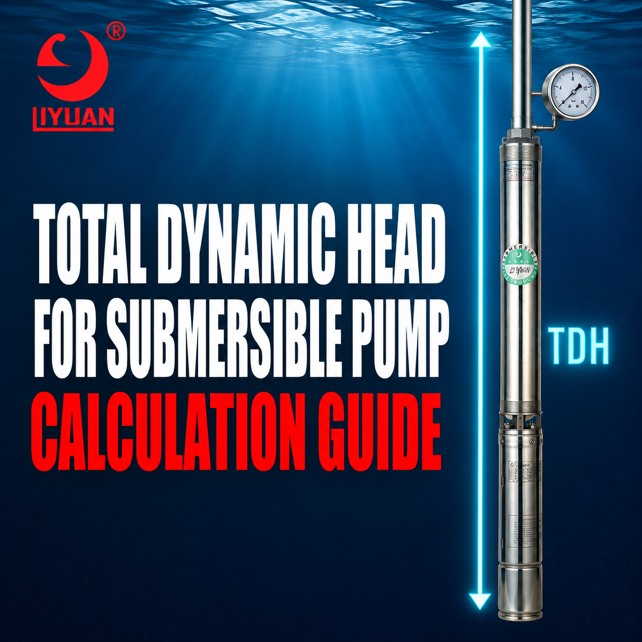
Total Dynamic Head For Submersible Pump Selection Is The Total Energy The Pump Must Add To Move Water At The Required Flow Rate.
For A Deep Well System, Total Dynamic Head Usually Includes Pumping Water Level, Vertical Elevation, Required Outlet Pressure, Drop-Pipe Friction, Discharge-Pipe Friction, And Losses From Valves And Fittings.
Do Not Use Pump Installation Depth As The Static Lift Unless It Actually Represents The Pumping Water Level.
Selecting A Pump With Incorrect Head Can Cause Low Flow, Excessive Flow, Motor Overload, Poor Efficiency, Unstable Pressure, And Premature Pump Failure.
What Is Total Dynamic Head?
Total Dynamic Head, Commonly Called TDH, Represents The Total Head A Pump Must Overcome At A Specific Flow Rate.
Head Expresses Hydraulic Energy As An Equivalent Height Of Water.
Manufacturers Usually Display Head In:
- Meters
- Feet
- Bar
- PSI
- Kilopascals
Pump Performance Curves Show The Relationship Between Flow And Head.
A Pump Does Not Produce Its Maximum Flow And Maximum Head At The Same Time. As Flow Increases, The Available Head Usually Decreases.
Therefore, Buyers Must Specify Both:
- Required Flow
- Required Total Dynamic Head
Total Dynamic Head Formula
A Practical Formula For A Deep Well Pump Is:
TDH = Static Lift + Pressure Head + Pipe-Friction Loss + Fitting Loss + Velocity Head
For Many Water-Well Applications, Velocity Head Is Small And Included With Other Hydraulic Losses.
A Simplified Formula Is:
TDH = Pumping Water Level + Discharge Elevation + Required Pressure Head + Total Friction Loss
Every Value Must Use The Same Unit, Such As Meters Or Feet.
Main Components Of Total Dynamic Head
Pumping Water Level
Pumping Water Level Is The Depth From The Selected Reference Point To The Water Surface While The Pump Operates At The Design Flow.
It Is Not The Same As Static Water Level.
The Pumping Water Level Accounts For Drawdown.
Discharge Elevation
Discharge Elevation Is The Vertical Distance From The Well Reference Point To The Final Delivery Point.
This Could Be:
- A Ground-Level Pressure Tank
- An Elevated Storage Tank
- An Irrigation Field
- A Building Fixture
- An Industrial Process Tank
- A Municipal Reservoir
Required Pressure Head
The System May Need Additional Pressure At The Delivery Point.
Examples Include:
- Residential Water Pressure
- Irrigation-Sprinkler Pressure
- Filter Operating Pressure
- Industrial Process Pressure
- Tank Inlet Pressure
- Reverse-Osmosis Feed Pressure
Pressure Must Be Converted Into Meters Or Feet Of Water Before Adding It To TDH.
Pipe-Friction Loss
Water Loses Energy As It Flows Through Pipework.
Friction Depends On:
- Flow Rate
- Pipe Length
- Internal Diameter
- Pipe Material
- Surface Roughness
- Water Temperature
- Pipe Age
- Flow Velocity
Fitting And Equipment Losses
Additional Head Loss Occurs Through:
- Elbows
- Tees
- Check Valves
- Gate Valves
- Ball Valves
- Filters
- Flow Meters
- Backflow Preventers
- Reducers
- Control Valves
- Tank Connections
These Losses Must Be Included At The Design Flow Rate.
Static Water Level Vs. Pumping Water Level
Static Water Level
1.Static Water Level Is The Water Depth When The Well Is Resting And The Pump Is Not Operating.
For Example, The Static Water Level May Be 20 Meters Below Ground.
Drawdown
Drawdown Is The Difference Between Static Water Level And Pumping Water Level.
As The Pump Removes Water, The Water Level Falls Until The Well Inflow And Pumping Rate Approach Equilibrium.
Pumping Water Level
Pumping Water Level Equals Static Water Level Plus Drawdown When Both Values Use Depth Below The Same Datum.
For Example:
- Static Water Level: 20 Meters
- Drawdown: 12 Meters
- Pumping Water Level: 32 Meters Below Ground
Use The Pumping Water Level For TDH Calculation.
Using Static Water Level Can Underestimate The Required Head And Result In Insufficient Flow.
Why Pump Installation Depth Is Not Static Lift
A Common Mistake Is Using The Pump’s Installation Depth As The Full Vertical Lift.
Assume:
- Pump Installation Depth: 100 Meters
- Pumping Water Level: 40 Meters
- Delivery Point: Ground Level
The Pump Does Not Need To Lift Water 100 Meters From Its Intake To Ground.
Pressure At The Submerged Pump Intake Includes The Water Column Above It. Therefore, The Main Static Lift Begins At The Pumping Water Surface.
In This Example, The Static Lift To Ground Is Approximately 40 Meters, Not 100 Meters.
However, Pump Depth Still Affects:
- Cable Length
- Drop-Pipe Length
- Pipe-Friction Loss
- Installation Cost
- Pump Submergence
- Motor Cooling
- Required Check Valves
The Drop-Pipe Friction Must Use The Actual Pipe Length, Even Though Static Lift Uses Pumping Water Level.
How To Convert Pressure Into Head
For Clean Water Near Normal Temperature:
- 1 PSI Is Approximately 2.31 Feet Of Water
- 1 Bar Is Approximately 10.2 Meters Of Water
- 1 Meter Of Water Is Approximately 0.098 Bar
- 1 Foot Of Water Is Approximately 0.433 PSI
PSI To Feet Of Head
Use:
Pressure Head In Feet = PSI × 2.31
For Example:
40 PSI × 2.31 = 92.4 Feet Of Head
Bar To Meters Of Head
Use:
Pressure Head In Meters = Bar × 10.2
For Example:
3 Bar × 10.2 = 30.6 Meters Of Head
These Conversions Apply Approximately To Water. Fluids With Different Density Require A Specific-Gravity Correction.
Metric TDH Calculation Example
Assume A Deep Well System Requires:
- Design Flow: 10 m³/h
- Static Water Level: 18 Meters Below Ground
- Drawdown At Design Flow: 12 Meters
- Delivery Point: 8 Meters Above Ground
- Required Outlet Pressure: 3 Bar
- Drop-Pipe Friction: 5 Meters
- Discharge-Pipe Friction: 3 Meters
- Valve And Fitting Loss: 1 Meter
Step 1: Calculate Pumping Water Level
18 Meters + 12 Meters = 30 Meters
Step 2: Calculate Static Lift
The Delivery Point Is 8 Meters Above Ground.
30 Meters + 8 Meters = 38 Meters
Step 3: Convert Outlet Pressure To Head
3 Bar × 10.2 = 30.6 Meters
Step 4: Calculate Total Friction Loss
5 Meters + 3 Meters + 1 Meter = 9 Meters
Step 5: Calculate Total Dynamic Head
TDH = 38 + 30.6 + 9
TDH = 77.6 Meters
The Required Duty Point Is Therefore Approximately:
10 m³/h At 78 Meters TDH
Select A Pump Whose Performance Curve Passes Through Or Near This Duty Point Within Its Recommended Operating Range.
Imperial TDH Calculation Example
Assume A Well System Requires:
- Design Flow: 15 GPM
- Pumping Water Level: 120 Feet Below Ground
- Delivery Point: 20 Feet Above Ground
- Required Outlet Pressure: 40 PSI
- Total Pipe And Fitting Loss: 18 Feet
Step 1: Calculate Static Lift
120 Feet + 20 Feet = 140 Feet
Step 2: Convert Pressure To Head
40 PSI × 2.31 = 92.4 Feet
Step 3: Add Friction Loss
TDH = 140 + 92.4 + 18
TDH = 250.4 Feet
The Required Pump Duty Is Approximately:
15 GPM At 250 Feet TDH
How To Calculate Pipe-Friction Loss
Pipe-Friction Loss Increases As Flow Velocity Increases.
It Also Increases When The Pipe Becomes:
- Longer
- Smaller
- Rougher
- More Restricted
- Internally Corroded
- Partially Blocked
Engineers Commonly Calculate Friction With:
- Darcy-Weisbach Equation
- Hazen-Williams Equation
- Manufacturer Friction Tables
- Hydraulic Design Software
Darcy-Weisbach Equation
The Darcy-Weisbach Equation Is:
Hf = F × (L ÷ D) × (V² ÷ 2G)
Where:
- Hf Is Friction Head Loss
- F Is Friction Factor
- L Is Pipe Length
- D Is Internal Pipe Diameter
- V Is Flow Velocity
- G Is Gravitational Acceleration
The Friction Factor Depends On Reynolds Number And Pipe Roughness.
Hazen-Williams Equation
The Hazen-Williams Method Is Common For Water-Piping Calculations.
It Uses:
- Flow Rate
- Pipe Diameter
- Pipe Length
- Pipe Roughness Coefficient
Use The Pipe’s Actual Internal Diameter, Not Only Its Nominal Size.
Why Internal Pipe Diameter Matters
Two Pipes With The Same Nominal Size Can Have Different Internal Diameters.
Differences May Result From:
- Pipe Material
- Wall Thickness
- Pressure Class
- Schedule
- Internal Lining
- Manufacturing Standard
A Small Reduction In Internal Diameter Can Significantly Increase Flow Velocity And Friction Loss.
Always Use Manufacturer Data For The Actual Pipe.
How To Calculate Fitting Losses
Fitting Losses Can Be Calculated With:
- Equivalent Pipe Length
- Resistance Coefficient
- Manufacturer Pressure-Drop Data
Equivalent-Length Method
Each Fitting Is Converted Into An Equivalent Length Of Straight Pipe.
For Example, A Check Valve May Create The Same Resistance As Several Meters Or Feet Of Straight Pipe.
Add The Equivalent Length To The Actual Pipe Length Before Calculating Friction.
Resistance-Coefficient Method
The Resistance-Coefficient Method Uses:
Hf = K × (V² ÷ 2G)
Where K Represents The Fitting’s Resistance Coefficient.
K Values Vary According To Fitting Design, Size, And Opening Position.
Which Components Add Friction Loss?
Include Every Significant Component Between The Pump And Delivery Point.
Common Components Include:
- Drop Pipe
- Discharge Pipe
- Check Valves
- Elbows
- Tees
- Reducers
- Isolation Valves
- Control Valves
- Water Meters
- Filters
- Backflow Preventers
- Heat Exchangers
- Sprinklers
- Nozzles
- Tank Connections
A Submersible Pump Check Valve Adds Head Loss That Increases With Flow.
What Is Velocity Head?
Velocity Head Represents The Kinetic Energy Of Moving Water.
The Formula Is:
Velocity Head = V² ÷ 2G
Velocity Head May Be Small In A Properly Sized Water System.
However, It Can Matter When:
- Pipe Velocity Is High
- Inlet And Outlet Diameters Differ
- Water Discharges Through A Nozzle
- Accurate Pump Testing Is Required
- Large Flow Rates Are Present
Do Not Automatically Ignore Velocity Head In High-Velocity Applications.
What Is A System Curve?
A System Curve Shows The Head Required By The System At Different Flow Rates.
Static Head And Pressure Head Remain Relatively Constant.
Friction Head Increases As Flow Increases.
Therefore, The System Curve Usually Rises As It Moves To The Right.
The Pump Curve Shows The Head A Pump Can Produce At Different Flow Rates.
The Point Where The Pump Curve Intersects The System Curve Is The Operating Point.
According To The Hydraulic Institute’s Total Head Explanation, Total Head Defines The Energy Required By The System And Supports Correct Pump Selection And Performance Evaluation.
How To Read A Submersible Pump Curve
A Typical Pump Curve Includes:
- Flow On The Horizontal Axis
- Head On The Vertical Axis
- Efficiency Curves
- Motor Power
- Stage Quantity
- Recommended Operating Range
- Impeller Diameter
- Pump-Speed Information
Locate The Required Flow On The Horizontal Axis.
Move Vertically Until You Reach The Pump Curve.
Then Read The Available Head On The Vertical Axis.
The Pump Curve Should Meet The Required Flow And TDH Within The Recommended Operating Range.
A Deep Well Submersible Pump Buyer Guide Provides Additional Selection Information.
Why Maximum Head Is Not The Same As TDH
Maximum Head Usually Represents The Pump’s Shutoff Head At Zero Or Very Low Flow.
TDH Represents The Actual System Requirement At The Design Flow.
A Pump With A Maximum Head Of 100 Meters May Produce Much Less Head At Its Rated Flow.
Never Select A Pump Using Only Maximum Head.
Instead, Select It According To:
- Required Flow
- Required TDH
- Pump Curve
- Motor Power
- Efficiency
- Recommended Operating Range
What Is Shutoff Head?
Shutoff Head Is The Head Produced When The Discharge Flow Approaches Zero.
A Pump Should Not Normally Operate At Shutoff For Extended Periods.
Extended Low-Flow Operation Can Cause:
- Water Heating
- Internal Recirculation
- Vibration
- Bearing Stress
- Seal Damage
- Motor Loading Problems
Shutoff Head Also Helps Determine The Maximum Pressure The System May Experience.
Pipes, Tanks, Valves, And Fittings Must Have Suitable Pressure Ratings.
How Does Flow Affect Total Dynamic Head?
Static Head Does Not Change Significantly With Flow Unless Water Levels Or Tank Levels Change.
Friction Head Increases As Flow Increases.
Therefore:
- Low Flow Produces Lower Friction Loss
- High Flow Produces Higher Friction Loss
- Higher Friction Raises TDH
- Higher TDH Can Reduce Actual Pump Flow
A High Flow Deep Well Pump Requires Accurate Pipe And Fitting Data.
How Does Drawdown Affect TDH?
As Well Water Level Falls, Static Lift Increases.
For Example:
- Pumping Water Level At Low Flow: 25 Meters
- Pumping Water Level At High Flow: 40 Meters
The Higher Flow Adds 15 Meters Of Static Lift Before Considering Additional Friction.
Therefore, The Well’s Sustainable Yield And Drawdown Test Are Essential For Correct Pump Selection.
How Does An Elevated Tank Affect TDH?
For An Open Elevated Tank, Calculate Static Lift From Pumping Water Level To The Maximum Tank Water Level.
The Tank’s Water Surface Changes As The Tank Fills And Empties.
Therefore, Calculate At Least:
- Minimum Tank Level
- Maximum Tank Level
The Pump Operating Point Changes As Tank Level Changes.
How Does A Pressure Tank Affect TDH?
For A Fixed-Speed Pressure-Tank System, The Pump Starts At Cut-In Pressure And Stops At Cut-Out Pressure.
The Required Head Changes During The Cycle.
Calculate Pump Performance At:
- Cut-In Pressure
- Cut-Out Pressure
- Minimum Pumping Water Level
- Maximum Pumping Water Level
The Pump Must Provide Suitable Flow Across The Complete Range.
How Does Irrigation Pressure Affect TDH?
Irrigation Equipment Requires Minimum Operating Pressure.
Include Pressure Requirements For:
- Sprinklers
- Drip Regulators
- Center Pivots
- Filters
- Fertilizer Injectors
- Control Valves
- Elevation Changes
The Agricultural Applications Of Deep Well Submersible Pumps Guide Explains Additional Irrigation Requirements.
How Do Filters Affect TDH?
A Clean Filter Adds A Certain Pressure Loss.
As The Filter Collects Material, Its Pressure Drop increases.
Calculate The System With:
- Clean-Filter Pressure Loss
- Normal Operating Loss
- Maximum Permitted Dirty-Filter Loss
Ignoring Dirty-Filter Pressure Can Produce Insufficient Downstream Flow.
How Does A VFD Affect Total Dynamic Head?
A VFD Changes Pump Speed.
According To The Affinity Laws:
- Flow Changes Approximately With Speed
- Head Changes Approximately With Speed Squared
- Power Changes Approximately With Speed Cubed
Reducing Speed Lowers The Pump Curve.
The System Curve Does Not Disappear. The VFD Adjusts Speed Until The Pump Curve Intersects The System Curve At The Required Control Point.
The Drive Must Respect Minimum Speed, Motor Cooling, Pump Thrust, And Flow Requirements.
How To Add A Selection Margin
A Small Design Allowance May Account For Reasonable Uncertainty In:
- Water-Level Changes
- Pipe Aging
- Fitting Data
- Filter Loading
- Future Minor Changes
- Measurement Accuracy
However, Adding A Large Arbitrary Margin Can Oversize The Pump.
An Oversized Pump May Cause:
- Excessive Flow
- Motor Overload
- Higher Energy Consumption
- Valve Throttling
- Water Hammer
- Short Cycling
- Poor Efficiency
Use Accurate Data Instead Of Adding Excessive Safety Margin.
Selecting Pump Stages From TDH
A Multistage Submersible Pump Uses Several Impellers And Diffusers.
Each Stage Adds Head.
More Stages Generally Produce Higher Total Head At The Same Flow.
However, Stage Selection Must Follow Manufacturer Curves.
Do Not Estimate Final Pump Performance By Multiplying One Stage’s Maximum Head Without Considering The Actual Duty Point And Pump Design.
Selecting Motor Power From Flow And Head
Higher Flow And Head Usually Require More Hydraulic Power.
A Simplified Hydraulic-Power Relationship Is:
Hydraulic Power = Density × Gravity × Flow × Head
Motor Selection Must Also Consider:
- Pump Efficiency
- Motor Efficiency
- Service Factor
- Maximum Pump Power
- Voltage
- Number Of Phases
- Operating Temperature
- VFD Operation
An Energy Efficient Submersible Pump Should Operate Near Its Recommended Efficiency Range.
Common TDH Calculation Mistakes
Using Total Well Depth
Total Well Depth Does Not Determine Static Lift.
Use Pumping Water Level And Delivery Elevation.
Using Pump Installation Depth Twice
Pump Setting Depth Affects Drop-Pipe Friction, But It Should Not Be Added Again As Static Lift.
Using Static Water Level
Static Water Level Does Not Include Drawdown.
Use The Expected Pumping Water Level At Design Flow.
Ignoring Required Outlet Pressure
A Pump Delivering To A Pressurized System Must Overcome Both Elevation And Pressure.
Ignoring Pipe Friction
Long Or Small-Diameter Pipes Can Produce Significant Head Loss.
Ignoring Fittings
Check Valves, Filters, Elbows, And Meters Can Add Meaningful Resistance.
Using Maximum Pump Head
Maximum Head At Zero Flow Is Not The Required Operating Point.
Confusing Pressure With Head
Convert Pressure Into Meters Or Feet Before Adding It To Other Head Components.
Ignoring Changing Conditions
Water Level, Tank Level, Filter Condition, And Flow Demand Can Change During Operation.
How To Verify TDH After Installation
Measure:
- Pump Flow
- Pumping Water Level
- Discharge Pressure
- Delivery Elevation
- Motor Current
- Input Power
- Valve Position
Convert Discharge Pressure Into Head.
Then Account For Water Level, Elevation, And Measurement Locations.
Compare The Result With The Manufacturer’s Pump Curve.
If Measured Flow Differs Significantly From Expected Flow, Check:
- Water Level
- Pump Rotation
- Pipe Leakage
- Check-Valve Condition
- Voltage
- Frequency
- Pump Wear
- Blocked Filters
- Incorrect Curve
- Measurement Accuracy
Information Required For Pump Selection
Provide The Following Data To The Pump Manufacturer:
- Required Flow
- Static Water Level
- Expected Drawdown
- Pumping Water Level
- Well Depth
- Pump Installation Depth
- Delivery Elevation
- Required Outlet Pressure
- Drop-Pipe Length
- Drop-Pipe Diameter
- Discharge-Pipe Length
- Discharge-Pipe Diameter
- Pipe Material
- Valve And Fitting Quantity
- Filter Pressure Loss
- Water Temperature
- Sand Content
- Supply Voltage
- Number Of Phases
- Control Method
- Daily Operating Hours
Complete Data Helps The Manufacturer Select The Pump, Motor, Cable, Pipe, And Control Equipment Correctly.
Frequently Asked Questions
What Is Total Dynamic Head For A Submersible Pump?
It Is The Total Head The Pump Must Overcome At The Required Flow. It Includes Static Lift, Pressure Head, Pipe Friction, Fitting Losses, And Other Hydraulic Resistance.
Should I Use Well Depth To Calculate TDH?
No. Use Pumping Water Level Rather Than Total Well Depth. Use Actual Pipe Length Separately When Calculating Friction.
Should I Use Static Or Pumping Water Level?
Use Pumping Water Level At The Design Flow. Static Water Level Does Not Include Drawdown.
Is Pump Depth Included In TDH?
Pump Depth Is Not Normally Used Directly As Static Lift. However, It Affects Drop-Pipe Length, Friction Loss, Cable Length, And Pump Submergence.
How Many Feet Of Head Equal One PSI?
For Water, One PSI Is Approximately 2.31 Feet Of Head.
How Many Meters Of Head Equal One Bar?
For Water, One Bar Is Approximately 10.2 Meters Of Head.
Does Pipe Friction Change With Flow?
Yes. Friction Loss Increases Rapidly As Flow And Velocity Increase.
Is Maximum Pump Head The Same As TDH?
No. Maximum Head Usually Occurs Near Zero Flow. TDH Is The System Head Required At The Design Flow.
Can I Select A Pump With Much Higher Head?
Excessive Head Can Cause High Flow, Motor Overload, High Pressure, Throttling Losses, And Reduced Efficiency.
Does A VFD Reduce TDH?
A VFD Does Not Change The Physical Static Head. It Changes Pump Speed And The Available Pump Head To Match System Demand.
Choose A Correctly Sized Deep Well Pump From Liyuan
Liyuan Manufactures Submersible Water Pumps For Wells, Deep Well Motors, Solar Pump Systems, And Control Solutions.
Liyuan Can Select A Pump According To:
- Required Flow
- Total Dynamic Head
- Well Diameter
- Pumping Water Level
- Pipe Size
- Water Quality
- Motor Voltage
- Control Method
- Application Requirements
Providing Complete Hydraulic Data Helps Liyuan Match The Pump, Motor, Stages, Cable, And Control Equipment.
Conclusion
Total Dynamic Head For Submersible Pump Selection Includes Pumping Water Level, Delivery Elevation, Required Outlet Pressure, Pipe Friction, And Fitting Losses.
Use Pumping Water Level Instead Of Static Water Level Or Total Well Depth.
Calculate Friction With The Actual Pipe Length, Internal Diameter, Material, And Design Flow.
Convert PSI Or Bar Into Feet Or Meters Before Adding Pressure To The TDH Calculation.
Finally, Select A Pump Whose Performance Curve Meets The Required Flow And TDH Within Its Recommended Operating Range.
Accurate TDH Calculation Improves Flow, Energy Efficiency, Motor Reliability, And The Service Life Of The Complete Deep Well Pump System.
Email:Liyuan@liyuan-pump.com
WhatsApp:+86 181-2828-2767