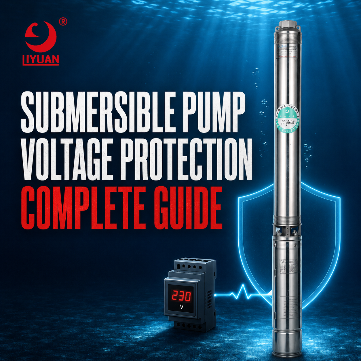
Submersible Pump Voltage Protection: Complete Guide
Submersible Pump Voltage Protection Prevents Motor Damage By Disconnecting The Pump When Supply Voltage Becomes Too Low, Too High, Unbalanced, Or Unstable.
A Reliable Protection System Should Monitor Voltage While The Motor Starts And Runs. Three-Phase Systems Should Also Detect Phase Loss, Phase Reversal, And Voltage Imbalance.
Correct Protection Settings Reduce Winding Failure, Cable Overheating, Contactor Damage, Nuisance Tripping, And Unexpected Pump Downtime.
However, A Voltage Relay Cannot Correct A Poor Power Supply. Technicians Must Also Identify Problems In Transformers, Generators, Power Cables, Terminals, Contactors, And Distribution Networks.
What Is Submersible Pump Voltage Protection?
Submersible Pump Voltage Protection Is A Control Function That Continuously Monitors The Electrical Supply Connected To A Pump Motor.
The System Compares Measured Voltage With Preset Operating Limits. If Voltage Moves Outside The Safe Range, The Controller Stops The Motor.
Depending On The Equipment, It Can Detect:
- Undervoltage
- Overvoltage
- Phase Loss
- Phase Reversal
- Voltage Imbalance
- Incorrect Phase Sequence
- Rapid Voltage Fluctuation
- Excessive Restart Frequency
- Unstable Generator Output
- Certain Power-Supply Faults
Advanced Controllers Can Record The Fault Type, Measured Voltage, Trip Time, And Restart History.
These Records Help Technicians Identify Whether The Problem Comes From The Utility Supply, Generator, Cable, Control Panel, Or Motor.
Why Do Submersible Pumps Need Voltage Protection?
A Submersible Motor Usually Operates Deep Inside A Well, Tank, Reservoir, Or Borehole.
Operators Cannot Easily Inspect The Motor While It Runs. Therefore, A Power-Supply Problem May continue Until The Motor Overheats Or Stops Completely.
Retrieving A Failed Pump Can Require:
- Lifting Equipment
- Skilled Technicians
- New Power Cable
- Pump Disassembly
- Well Downtime
- Replacement Components
- Additional Installation Labor
Correct Voltage Protection Is Especially Important For Agricultural Irrigation, Municipal Water Supply, Industrial Processing, And Other Continuous-Duty Systems.
Proper Protection Also Extends The Service Life Of Deep Well Submersible Motors.
What Voltage Problems Can Damage A Submersible Pump?
Low Voltage
Low Voltage Reduces The Motor’s Ability To Produce Starting And Running Torque.
The Motor May Attempt To Compensate By Drawing More Current. As A Result, The Windings, Cable, Contactors, And Starting Components Can Overheat.
Common Causes Of Low Voltage Include:
- An Overloaded Transformer
- An Undersized Generator
- Excessive Cable Length
- An Undersized Power Cable
- Loose Electrical Connections
- Damaged Contactor Contacts
- Weak Utility Supply
- Excessive Simultaneous Loads
- Incorrect Transformer Taps
- Poor Cable Splices
- An Undersized Extension Circuit
Low Voltage Can Become More Severe During Motor Starting Because Starting Current Creates An Additional Voltage Drop.
Therefore, Technicians Should Measure Voltage Both Before Starting And While The Pump Is Operating.
High Voltage
High Voltage Places Additional Electrical Stress On Motor Insulation, Capacitors, Contactors, And Electronic Controllers.
It Can Increase Magnetizing Current, Motor Temperature, Noise, And Winding Stress.
Possible Causes Include:
- Incorrect Transformer Connections
- Incorrect Transformer Tap Settings
- Unstable Generator Regulation
- Incorrect VFD Parameters
- Lightly Loaded Distribution Circuits
- Neutral Connection Problems
- Faulty Voltage Regulators
The Protection Device Should Disconnect The Pump If Voltage Remains Above The Motor Manufacturer’s Approved Limit.
Voltage Imbalance
Voltage Imbalance Occurs When The Three Line-To-Line Voltages Are Not Equal.
For Example, A Three-Phase System May Produce Different Measurements Between:
- Phase L1 And Phase L2
- Phase L2 And Phase L3
- Phase L3 And Phase L1
Even A Small Voltage Imbalance Can Create A Much Larger Current Imbalance.
According To Fluke’s Voltage Unbalance Guide, Voltage Imbalance Can Cause Higher Motor Current, Torque Pulsation, Vibration, Mechanical Stress, Additional Losses, And Overheating.
Possible Causes Include:
- Uneven Single-Phase Loads
- Loose Terminals
- Worn Contactor Contacts
- A Damaged Fuse Holder
- Transformer Problems
- Unequal Cable Resistance
- Poor Cable Splices
- Supply Network Imbalance
Voltage Imbalance Should Be Corrected At Its Source. Increasing The Motor Overload Setting Does Not Solve The Problem.
Phase Loss
Phase Loss Occurs When One Phase Of A Three-Phase Supply Becomes Disconnected.
The Motor May Fail To Start, Or A Running Motor May Continue Operating On The Remaining Phases. This Condition Can Produce Severe Current Imbalance And Rapid Winding Overheating.
Typical Causes Include:
- A Blown Fuse
- A Failed Contactor Pole
- A Loose Terminal
- A Broken Conductor
- A Damaged Cable Joint
- A Transformer Fault
- A Faulty Circuit Breaker Contact
- A Disconnected Generator Phase
A Phase-Loss Relay Should Stop The Motor Before Serious Damage Occurs.
Phase Reversal
Phase Reversal Changes The Rotational Direction Of A Three-Phase Motor.
It Commonly Occurs When Two Supply Phases Are Exchanged During Installation Or Maintenance.
Incorrect Rotation Can Cause:
- Reduced Pump Flow
- Reduced Discharge Pressure
- Poor Pump Efficiency
- Abnormal Noise
- Increased Mechanical Stress
- Possible Pump Damage
A Phase-Sequence Relay Can Prevent Operation When The Phase Order Is Incorrect.
Voltage Fluctuation
Rapid Voltage Changes Can Cause Contactors To Drop Out And Reconnect repeatedly.
The Motor May Experience Multiple Starts Within A Short Period. Every Start Produces High Current And Additional heat.
Voltage Fluctuation Can Result From:
- Unstable Generators
- Weak Distribution Networks
- Large Nearby Electrical Loads
- Faulty Contactors
- Loose Connections
- Incorrect Control Wiring
- Inadequate Transformer Capacity
A Restart Delay And Maximum Start Limit Can Prevent Repeated Cycling After An Unstable Supply.
Voltage Surges
A Voltage Surge Is A Short-Duration Increase In Electrical Potential.
Potential Sources Include:
- Lightning
- Utility Switching
- Large Motor Switching
- Capacitor Bank Switching
- Generator Connection Changes
- Inductive Load Interruption
A Standard Undervoltage Or Overvoltage Relay May Not React Fast Enough To A Very Short Transient.
Surge Protective Devices, Grounding, Bonding, And Lightning Protection May Therefore Be Required In Addition To Normal Motor Voltage Protection.
What Happens When Voltage Is Too Low?
When Supply Voltage Drops, The Motor May Produce Less Torque.
If The Pump Requires More Torque Than The Motor Can Deliver, The Motor Slows Down Or Fails To Accelerate. Current Then Increases And Creates Additional Winding Heat.
Possible Symptoms Include:
- Slow Starting
- Motor Humming
- Overload Trips
- Reduced Pump Output
- Unstable Discharge Pressure
- Hot Cables
- Burned Contactors
- Failed Capacitors
- Frequent Controller Faults
- Motor Winding Damage
Low Voltage At The Control Panel Does Not Always Equal The Voltage Reaching The Motor.
A Long Submersible Cable Produces Voltage Drop. The Actual Motor-Terminal Voltage May Be Lower Than The Panel Measurement, Especially Under Full Load.
What Happens When Voltage Is Too High?
Excessive Voltage Increases Electrical Stress Across The Motor Windings.
It Can Also Affect:
- Control Transformers
- Capacitors
- Contactors
- VFD Components
- Electronic Relays
- Cable Insulation
- Motor Insulation
- Surge Devices
High Voltage May Not Cause An Immediate Failure. However, Long-Term Exposure Can Accelerate Insulation Aging And Reduce Motor Service Life.
The Motor Must Operate Within The Voltage Range Specified By Its Manufacturer.
What Is An Acceptable Voltage Range?
There Is No Universal Voltage Limit For Every Submersible Motor.
The Acceptable Range Depends On:
- Motor Design
- Rated Voltage
- Rated Frequency
- Motor Power
- Number Of Phases
- Service Factor
- Water Temperature
- Cooling Conditions
- Starting Method
- VFD Operation
- Manufacturer Requirements
Some Motors Permit Operation Within A Defined Percentage Of Rated Voltage. However, That Value Should Never Be Applied To Every Motor Without Checking Its Technical Documentation.
The Correct Approach Is To:
- Read The Motor Nameplate.
- Check The Manufacturer’s Manual.
- Measure Voltage Under Full Load.
- Calculate Cable Voltage Drop.
- Confirm Voltage At Every Operating Condition.
- Set The Relay Within The Approved Range.
How Is Voltage Imbalance Calculated?
Voltage Imbalance Can Be Calculated With The Following Method:
Voltage Imbalance Percentage = Maximum Deviation From Average Voltage ÷ Average Voltage × 100
For Example, Assume The Three Measurements Are:
- L1 To L2: 397 Volts
- L2 To L3: 400 Volts
- L3 To L1: 403 Volts
The Average Is 400 Volts.
The Maximum Deviation From The Average Is 3 Volts.
Therefore:
Voltage Imbalance = 3 ÷ 400 × 100 = 0.75%
Always Compare The Calculated Result With The Motor And Controller Manufacturer’s Limits.
Technicians Should Also Measure All Three Phase Currents. A Balanced Voltage Supply Does Not Guarantee Balanced Motor Current If The Cable, Connections, Or Windings Are Damaged.
Main Types Of Submersible Pump Voltage Protection
Voltage Monitoring Relay
A Voltage Monitoring Relay Measures Supply Voltage And Opens The Control Circuit When Voltage Moves Outside The Selected Range.
Depending On The Model, It May Provide:
- Undervoltage Protection
- Overvoltage Protection
- Phase-Loss Protection
- Phase-Reversal Protection
- Voltage-Imbalance Protection
- Adjustable Trip Delay
- Adjustable Restart Delay
A Delay Prevents Nuisance Trips During Brief Supply disturbances. However, The Delay Must Not Be So Long That It Exposes The Motor To Damage.
Electronic Motor Protector
An Electronic Motor Protector Combines Voltage Monitoring With Current And Load Monitoring.
It May Detect:
- High Voltage
- Low Voltage
- Phase Loss
- Phase Reversal
- Voltage Imbalance
- Current Imbalance
- Overload
- Underload
- Locked Rotor
- Excessive Cycling
- Ground Fault
- Dry Running
Combined Protection Provides A More Complete Picture Of Motor Operation Than A Simple Voltage Relay.
The Franklin Electric IPS-RV Intelligent Pump Soft Starter Is One Example Of A Pump Controller That Integrates Under-And-Overvoltage, Phase-Loss, Phase-Imbalance, Overload, And Dry-Run Functions.
Phase Monitoring Relay
A Phase Monitoring Relay Is Designed Primarily For Three-Phase Systems.
It Detects:
- Missing Phases
- Incorrect Phase Sequence
- Excessive Voltage Imbalance
- High Voltage
- Low Voltage
This Device Is Particularly Important When The Pump Uses A Direct-On-Line Starter Or A Basic Contactor Panel.
Surge Protective Device
A Surge Protective Device Diverts Short-Duration Transient Energy Away From Sensitive Equipment.
It Does Not Replace An Overvoltage Relay. Instead, The Two Devices Protect Against Different Types Of Events.
A Complete Installation May Require Surge Protection At:
- The Main Distribution Panel
- The Pump Control Panel
- The VFD Input
- Signal And Sensor Circuits
- Remote Communication Lines
Installation Should Follow Local Electrical Codes And The Surge-Device Manufacturer’s Instructions.
Variable Frequency Drive
A VFD Can Monitor Input Voltage, Internal DC-Bus Voltage, Motor Current, And Drive Output Conditions.
Depending On The Model, It May Provide:
- Input Undervoltage Protection
- Input Overvoltage Protection
- Phase-Loss Detection
- Motor Overload Protection
- Ground-Fault Protection
- Current Limiting
- Restart Delay
- Fault History
- Dry-Run Detection
However, VFD Parameters Must Match The Motor And Pump.
Incorrect Rated Voltage, Base Frequency, Maximum Frequency, Or Acceleration Time Can Create New Electrical Problems.
Submersible Pump Control Box
An Electric Control Box For A Submersible Pump Can Include Voltage Relays, Contactors, Circuit Breakers, Capacitors, Overload Devices, Phase Monitors, And Automatic Controls.
The Control Box Must Match:
- Motor Power
- Rated Voltage
- Motor Current
- Supply Phase
- Starting Method
- Control Method
- Installation Environment
- Required Protection Functions
A Control Box Designed For One Motor Should Not Be Connected To A Different Motor Without Confirming Component Compatibility.
Single-Phase Pump Voltage Protection
Single-Phase Submersible Pumps Are Common In Residential Wells, Small Farms, And Light Commercial Systems.
They Are Particularly Sensitive To:
- Long Cable Runs
- Low Utility Voltage
- Undersized Generators
- Incorrect Capacitors
- Failed Starting Relays
- Loose Neutral Connections
- Frequent Starting
A Single-Phase Protection System Should Monitor Both Voltage And Motor Current.
Three-Wire Single-Phase Motors Also Require A Correctly Matched Control Box. Incorrect Start Or Run Capacitors Can Cause Slow Acceleration And Excessive Current.
The Single Phase Submersible Pump Vs. Three Phase Pump Guide Explains Which Power System Is More Suitable For Different Applications.
Three-Phase Pump Voltage Protection
Three-Phase Motors Require More Comprehensive Monitoring Because A Problem Can Affect Only One Phase.
The Protection Device Should Ideally Monitor:
- All Three Line-To-Line Voltages
- All Three Phase Currents
- Phase Sequence
- Phase Loss
- Voltage Imbalance
- Current Imbalance
- Starting Time
- Running Current
- Restart Frequency
Measuring Only One Voltage Or One Current Can Miss A Serious Fault.
Three-Phase Protection Is Particularly Important For Large Agricultural, Industrial, And Municipal Pumping Systems.
How Does Cable Size Affect Pump Voltage?
Every Power Cable Has Electrical Resistance.
As Current Travels Through A Long Cable, Resistance creates Voltage Drop. The Longer The Cable And The Higher The Current, The Greater The Potential Drop.
An Undersized Cable Can Cause:
- Low Motor-Terminal Voltage
- High Motor Current
- Difficult Starting
- Cable Heating
- Reduced Motor Torque
- Overload Trips
- Winding Damage
Cable Selection Should Consider:
- Motor Full-Load Current
- Starting Current
- Cable Length
- Installation Method
- Conductor Material
- Ambient Temperature
- Voltage-Drop Limit
- Local Electrical Codes
Connections And Splices Must Also Remain Clean, Tight, Waterproof, And Electrically Stable.
How Do Generators Affect Pump Voltage?
Generators Must Provide Enough Capacity For Both Running And Starting Conditions.
A Generator May Show Correct Voltage Before The Pump Starts. However, Voltage Can Drop Severely When The Motor Draws Starting Current.
An Undersized Generator Can Cause:
- Slow Motor Acceleration
- Contactor Chatter
- Controller Resetting
- Low-Voltage Trips
- High Motor Current
- Generator Instability
- Excessive Frequency Drop
Generator Selection Should Consider:
- Motor Starting Method
- Motor Starting Current
- Other Connected Loads
- Generator Voltage Regulation
- Power Factor
- Required Starting Torque
A Soft Starter Or VFD Can Reduce Starting Stress, But The Generator Must Still Meet The Manufacturer’s System Requirements.
How Does Voltage Protection Work In Solar Pump Systems?
Solar-Powered Pump Systems Experience Changing Input Power As Sunlight Conditions Vary.
A Solar Pump Controller Converts Solar Array Power Into A Suitable Motor Supply. It May also include:
- Low-Input-Voltage Protection
- High-Input-Voltage Protection
- Dry-Run Protection
- Overcurrent Protection
- Overtemperature Protection
- Automatic Restart
- Maximum Power Point Tracking
- Motor Phase Protection
The Solar Array Voltage Must Remain Within The Controller’s Approved Input Range.
Too Few Panels May Prevent Starting During Weak Sunlight. Too Many Series-Connected Panels May Exceed The Controller’s Maximum Input Voltage.
A Properly Designed Water Pump With Solar Power Should Match The Pump, Motor, Controller, Solar Array, Total Head, And Daily Water Demand.
How Should Voltage Protection Settings Be Selected?
Settings Should Follow The Motor And Controller Manufacturer’s Instructions.
Important Parameters Include:
- Rated Motor Voltage
- Minimum Operating Voltage
- Maximum Operating Voltage
- Voltage-Imbalance Limit
- Trip Delay
- Restart Delay
- Phase-Loss Response
- Automatic Restart Limit
- Maximum Starts Per Hour
- Fault Reset Method
The Settings Should Allow Normal Starting Conditions Without Exposing The Motor To Dangerous Voltage.
A Short Restart Delay May Cause The Pump To Restart Before The Well Recovers Or Before The Motor Cools.
An Unlimited Automatic Restart Function Can also produce repeated starting during An Unstable Power Supply.
Manual Reset Vs. Automatic Reset
A Manual-Reset System Requires An Operator To Inspect The Fault Before Restarting The Pump.
This Method Is Often Suitable For:
- Industrial Systems
- Critical Water-Supply Equipment
- Repeated Electrical Faults
- Systems Requiring Operator Supervision
An Automatic-Reset System Can Restart The Pump After Voltage Returns To Normal.
This Method May Be Useful For Remote Wells And Unattended Agricultural Systems. However, It Should Include:
- A Restart Delay
- A Maximum Restart Limit
- Fault Logging
- Dry-Run Recovery Time
- Appropriate Safety Interlocks
- Remote Alarm Functions
Automatic Restart Must Not Create A Risk For Personnel Or Equipment.
How To Troubleshoot A Pump Voltage Fault
1. Record The Fault
Record The Following Information Before Resetting The Controller:
- Fault Code
- Trip Time
- Measured Voltage
- Motor Current
- Pump Running Time
- Generator Status
- Water Level
- Other Connected Loads
- Weather Conditions
A Fault History Can Reveal Whether The Problem Occurs During Starting, Heavy Facility Demand, Generator Operation, Or Lightning Events.
2. Measure The Incoming Supply
Measure Voltage At The Main Supply And Pump Control Panel.
For Three-Phase Systems, Record All Three Line-To-Line Voltages.
Only Qualified Personnel Should Test Energized Electrical Equipment With Properly Rated Instruments And Protective Equipment.
3. Measure Voltage During Starting
A No-Load Voltage Measurement May Appear Normal Even When The Supply Cannot Start The Motor.
Measure The Voltage Drop During Motor Acceleration. A Severe Drop May Indicate:
- An Undersized Transformer
- An Undersized Generator
- Excessive Cable Resistance
- Loose Connections
- A Stalled Pump
- Excessive Starting Current
4. Measure Running Current
Measure Motor Current On Every Phase.
Compare The Results With The Motor Nameplate And Manufacturer’s Limits.
High Current On All Phases May Indicate Low Voltage, Hydraulic Overload, Or Mechanical Resistance.
Unequal Current May Indicate Voltage Imbalance, Cable Damage, Poor Connections, Or A Motor Winding Problem.
5. Inspect The Control Panel
Check:
- Fuse Holders
- Circuit Breakers
- Contactors
- Cable Terminals
- Voltage Relays
- Current Transformers
- Capacitors
- Control Transformers
- Surge Devices
- VFD Fault Logs
Discolored Terminals Or Burned Contacts May Indicate Heat And Excessive Resistance.
6. Inspect The Cable And Splices
A Damaged Cable Or Poor Splice Can Create Resistance, Leakage, Voltage Drop, And Phase Imbalance.
Check For:
- Water Entry
- Corrosion
- Loose Connections
- Damaged Insulation
- Incorrect Conductor Size
- Mechanical Damage
- Excessive Cable Length
7. Test The Motor
Perform Winding Resistance And Insulation Resistance Tests According To The Motor Manufacturer’s Procedure.
Disconnect The Motor From VFDs, Electronic Relays, Sensors, And Other Sensitive Components Before Applying An Insulation Tester.
The How To Check A Submersible Pump Motor Guide Provides More Detailed Testing Information.
8. Check The Hydraulic Load
An Electrical Trip Can Sometimes Result From A Pump Or Hydraulic Problem.
Check:
- Pump Flow
- Discharge Pressure
- Total Dynamic Head
- Valve Position
- Impeller Condition
- Sand Accumulation
- Bearing Condition
- Shaft Rotation
Understanding How A Submersible Pump Works Helps Technicians Separate Electrical Faults From Hydraulic Problems.
How To Prevent Future Voltage Problems
A Preventive Maintenance Program Should Include:
- Regular Voltage Measurements
- Three-Phase Imbalance Checks
- Motor Current Recording
- Terminal Tightness Inspections
- Contactor Contact Inspection
- Cable And Splice Testing
- Surge Protector Inspection
- Generator Load Testing
- Transformer Capacity Review
- VFD Fault-Log Review
- Control-Panel Cleaning
- Motor Insulation Testing
Maintenance Records Help Identify Gradual Changes Before They Cause A Complete Failure.
The Electric Submersible Pump Maintenance Guide Provides Additional Recommendations For Extending Pump Service Life.
Information Required When Selecting Voltage Protection
Provide The Following Information To The Pump Or Control-Panel Manufacturer:
- Pump Model
- Motor Model
- Rated Power
- Rated Voltage
- Rated Current
- Number Of Phases
- Supply Frequency
- Starting Method
- Cable Length
- Cable Size
- Transformer Capacity
- Generator Capacity
- Expected Voltage Variation
- Installation Location
- Water Temperature
- Maximum Starts Per Hour
- VFD Requirements
- Automatic Control Requirements
- Remote Monitoring Requirements
- Local Electrical Standards
Complete Information Helps The Supplier Select Suitable Relays, Contactors, Breakers, Surge Devices, Cables, And Controllers.
Frequently Asked Questions
Why Does My Submersible Pump Show A Low-Voltage Fault?
Possible Causes Include An Overloaded Transformer, Undersized Generator, Long Cable, Loose Connection, Damaged Contactor, Weak Utility Supply, Or Excessive Starting Load.
Can Low Voltage Burn A Pump Motor?
Yes. Low Voltage Can Reduce Motor Torque And Increase Current. Continued Operation Can Overheat The Windings And Damage The Motor.
Can High Voltage Damage A Submersible Pump?
Yes. High Voltage Can Increase Electrical Stress On The Motor Insulation, Capacitors, Control Components, And Power Cable.
Why Does Voltage Drop When The Pump Starts?
A Motor Draws High Current During Starting. If The Transformer, Generator, Cable, Or Connections Cannot Support That Demand, Supply Voltage Drops.
Does A Circuit Breaker Provide Voltage Protection?
A Standard Circuit Breaker Primarily Protects Against Short Circuits And Excessive Current. It Does Not Usually Provide Complete Under-And-Overvoltage, Phase-Loss, Or Voltage-Imbalance Protection.
Does A VFD Protect Against Voltage Problems?
Many VFDs Include Undervoltage, Overvoltage, Phase-Loss, And Current Protection. However, The Functions And Settings Vary Between Models.
What Causes Voltage Imbalance?
Common Causes Include Unequal Single-Phase Loads, Loose Connections, Worn Contactor Contacts, Transformer Problems, Damaged Fuses, And Unequal Cable Resistance.
Can I Increase The Voltage-Relay Delay To Prevent Trips?
The Delay Should Only Be Changed After Confirming The Motor And Controller Requirements. An Excessively Long Delay May Allow The Motor To Operate Under Dangerous Conditions.
Why Does The Pump Keep Restarting After A Voltage Fault?
The Controller May Have Automatic Reset Enabled. Check The Restart Delay, Maximum Restart Count, Supply Stability, And Fault History.
Is Surge Protection The Same As Overvoltage Protection?
No. Surge Protection Responds To Short Transient Events. An Overvoltage Relay Responds To A Sustained Voltage Above Its Selected Limit.
Choose Reliable Pump Protection With Liyuan
Liyuan Manufactures Deep Well Pumps, Submersible Motors, Solar Pump Systems, And Control Solutions For Residential, Agricultural, Commercial, Municipal, And Industrial Applications.
Each System Can Be Selected According To:
- Required Flow
- Total Dynamic Head
- Well Diameter
- Motor Power
- Supply Voltage
- Number Of Phases
- Cable Length
- Water Temperature
- Control Method
- Protection Requirements
Correctly Matching The Pump, Motor, Cable, And Control Panel Improves Reliability And Reduces The Risk Of Electrical Failure.
Conclusion
Submersible Pump Voltage Protection Is Essential For Preventing Motor Damage Caused By Low Voltage, High Voltage, Phase Loss, Phase Reversal, And Voltage Imbalance.
A Complete Protection System May Include A Voltage Relay, Phase Monitor, Electronic Motor Protector, Surge Device, Control Box, Or Variable Frequency Drive.
However, Protection Devices Cannot Correct An Undersized Cable, Weak Generator, Loose Connection, Or Unstable Transformer.
Always Measure Voltage During Starting And Full-Load Operation. For Three-Phase Systems, Measure Every Line-To-Line Voltage And Every Phase Current.
Correct Equipment Selection, Accurate Settings, And Regular Electrical Testing Help Extend Pump Life, Reduce Downtime, And Protect The Complete Deep Well Pumping System.
Email:Liyuan@liyuan-pump.com
WhatsApp:+86 181-2828-2767