What Is Submersible Pump Cavitation?
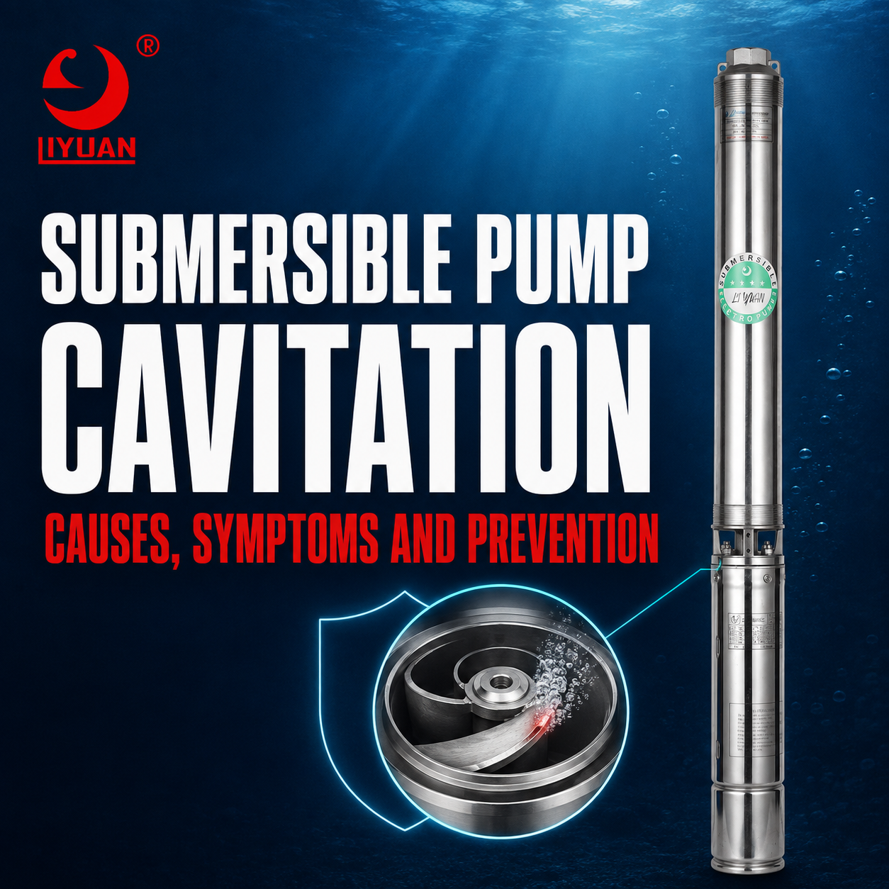
Submersible Pump Cavitation Occurs When Local Water Pressure Falls Below The Water’s Vapor Pressure. Vapor Bubbles Then Form Near The Pump Inlet Or Impeller Eye.
As These Bubbles Move Into A Higher-Pressure Area, They Collapse Rapidly. This Collapse Produces Shock Waves, Noise, Vibration, And Surface Damage.
Severe Cavitation Can Erode Impellers, Reduce Flow, Lower Head, Increase Energy Consumption, And Shorten Pump Life.
Deep Well Pumps Remain Submerged During Operation. However, Submergence Alone Does Not Guarantee Cavitation-Free Performance. Excessive Flow, Falling Water Levels, Restricted Inlets, High Water Temperature, And Incorrect Pump Selection Can still Create Low-Pressure Conditions.
The Most Effective Prevention Method Is Maintaining Adequate Inlet Pressure And Operating The Pump Within Its Recommended Flow Range.
How Cavitation Develops Inside A Submersible Pump
Water Enters The Pump Through The Inlet Screen And Moves Toward The First-Stage Impeller.
The Impeller Accelerates The Water. As Water Velocity Increases Near The Impeller Eye, Local Static Pressure Falls.
When This Pressure Drops Below The Water’s Vapor Pressure, Small Vapor-Filled Cavities Develop.
The Impeller Then Carries These Bubbles Into A Higher-Pressure Region. The Bubbles Collapse And Release Concentrated Energy.
If The Collapse Occurs Near An Impeller Blade, Diffuser, Or Pump Casing, Repeated Impacts can Remove Small Pieces Of Material.
Over Time, The Surface Develops A Rough, Pitted, Or Honeycomb-Like Appearance.
The Hydraulic Institute Explains That Vapor Bubbles Can Block Impeller Flow Areas, Reduce Pump Performance, And Cause Erosion When They Collapse.
What Is NPSH?
NPSH Means Net Positive Suction Head. It Describes The Pressure Available At The Pump Inlet Above The Liquid’s Vapor Pressure.
Two NPSH Values Require Attention:
- Net Positive Suction Head Available
- Net Positive Suction Head Required
Net Positive Suction Head Available
NPSHA Represents The Inlet Pressure Provided By The Actual Pumping System.
For A Deep Well Pump, NPSHA Depends On:
- Atmospheric Pressure
- Pump Submergence
- Pumping Water Level
- Water Temperature
- Inlet Velocity
- Intake Screen Losses
- Well Casing Conditions
- Site Altitude
Greater Pump Submergence Usually Increases NPSHA. However, A Falling Water Level Reduces The Pressure Available At The Pump Inlet.
Net Positive Suction Head Required
NPSHR Represents The Minimum Inlet Head Needed By A Specific Pump At A Particular Flow Rate.
The Pump Manufacturer Determines This Value Through Testing. NPSHR Usually Changes Across The Pump’s Performance Curve.
Higher Flow Rates Commonly Require More NPSH. Therefore, A Pump That Operates Safely At Normal Flow May Cavitate When Demand Forces It Toward Maximum Flow.
NPSHA Must Exceed NPSHR
A Basic Selection Condition Is:
NPSHA > NPSHR
However, A Small Numerical Difference May Not Provide Enough Protection.
Engineers Should Apply A Suitable NPSH Margin. The Correct Margin Depends On Pump Design, Application, operating range, Water Properties, Reliability Requirements, And Industry Standards.
Do Not Use One Fixed NPSH Margin For Every Installation.
Why NPSH3 Does Not Mean Cavitation Has Completely Stopped
Many Pump Curves Show NPSHR As NPSH3.
NPSH3 Represents The Inlet Condition That Produces A Three Percent Drop In First-Stage Head During A Standard Test.
Visible Or Detectable Cavitation Can Begin Before The Pump Reaches This Three Percent Head-Loss Point.
Therefore, Selecting A System With NPSHA Exactly Equal To Published NPSH3 Can Create An Unacceptable Risk.
A Practical Design Should Include Additional Margin For:
- Water-Level Variation
- Flow Measurement Error
- Pipe And Screen Fouling
- Pump Wear
- Water Temperature Changes
- Atmospheric Pressure Changes
- Higher-Than-Expected Flow
- Future System Modifications
Main Causes Of Submersible Pump Cavitation
Insufficient Pump Submergence
The Pump Must Remain Sufficiently Below The Lowest Pumping Water Level.
If The Water Level Approaches The Pump Inlet, Available Inlet Pressure decreases. The Pump May Also Create A Vortex That Pulls Air From The Water Surface.
Dynamic Water Level Matters More Than Static Water Level. A Well Can Appear Full Before Starting But Experience Significant Drawdown During Pumping.
Operators Should Measure The Pumping Water Level After The Well Reaches A Stable Operating Condition.
Excessive Flow Rate
Operating Too Far To The Right Of The Pump Curve Can Increase Inlet Velocity And NPSHR.
Excessive Flow May Result From:
- Oversized Pump Selection
- Low Discharge Resistance
- Incorrect Valve Settings
- Unexpectedly Low System Head
- Excessive Variable Frequency Drive Speed
- Incorrect Impeller Configuration
The Pump Should Operate Within The Manufacturer’s Recommended Range.
Use The Submersible Pump Flow Rate: Complete Sizing Guide To Determine A Suitable Capacity.
Excessive Well Drawdown
A Well Must Supply Water At A Rate That Supports The Pump’s demand.
If Pump Capacity Exceeds The Well’s Recovery Rate, The Pumping Water Level continues To Fall. This Process Reduces Submergence And Inlet Pressure.
Severe Drawdown Can Cause Cavitation, Air Entrainment, Dry Running, Or Complete Loss Of Water Supply.
A Smaller Pump, Lower Pump Speed, Storage Tank, Or Cyclic Control Strategy May Solve The Problem.
Restricted Inlet Screen
Sand, Mineral Deposits, Biological Growth, Debris, Or Corrosion Can Restrict The Pump Inlet.
A Restricted Screen Accelerates Water Through The Remaining Open Areas. It also Creates Additional Pressure Loss Before Water Enters The Impeller.
Operators Should Inspect Both The Pump Inlet Screen And The Well Screen.
Cleaning Only The Pump May Not Solve A Restriction Inside The Well Casing Or Aquifer Interface.
Incorrect Pump Position
A Pump Installed Too Close To The Well Bottom Can Draw Sediment, Sand, Or Debris Into The Inlet.
The Restricted Flow Around The Pump Can Reduce Inlet pressure. Sediment Can Also Block The Screen And Damage The Impellers.
The Installation Should Maintain Suitable Clearance Between The Pump Inlet And The Well Bottom.
The Required Clearance Depends On Well Construction, Sediment Conditions, Pump Size, And Manufacturer Recommendations.
High Water Temperature
Warm Water Has A Higher Vapor Pressure Than Cold Water. Therefore, Warm Water Requires More Inlet pressure To Prevent Vapor Formation.
A Pump That Operates Correctly With Cold Water May Cavitate In A Geothermal Well Or Hot-Water Application.
Engineers Must Use The Actual Maximum Water Temperature During NPSH Calculations.
For Elevated-Temperature Applications, Review The Hot Water Submersible Pump: Complete Selection Guide.
High Installation Altitude
Atmospheric Pressure Decreases As Elevation Increases.
Lower Atmospheric Pressure Reduces The Pressure Acting On The Water Surface. As A Result, The Pump Has Less Available Inlet Head.
Altitude Corrections Become Important In Mountainous Agricultural, Municipal, Mining, And Residential applications.
Poor Inlet Flow Conditions
Obstructions Near The Pump Inlet Can Create Uneven Velocity And Local Pressure Reduction.
Common Problems Include:
- Small Well Casing Clearance
- Damaged Cooling Shrouds
- Incorrect Flow Sleeves
- Debris Near The Inlet
- Cable Guards Blocking Flow
- Sediment Accumulation
- Nearby Pipe Connections
- Unstable Approach Flow
Uniform Water Entry Helps The First-Stage Impeller Operate efficiently.
Incorrect Variable Frequency Drive Settings
A Variable Frequency Drive Can Control Flow And Protect A Well From Excessive Drawdown. However, Incorrect Settings Can Increase Cavitation Risk.
Increasing Motor Speed Above The Rated Value raises Flow, Head, Power Demand, And NPSHR.
The Drive Should Limit Maximum Frequency According To Pump And Motor specifications.
A Pressure-Control System Should Also Avoid Rapid Speed changes And Unstable Hunting.
Read The Variable Frequency Drive For Submersible Pump: Complete Guide Before Programming A Drive.
Common Symptoms Of Pump Cavitation
Gravel-Like Noise
Cavitation Often Produces A Crackling, Popping, Or Gravel-Like Sound.
However, A Deep Well Installation Can Make This Sound Difficult To Hear At The Surface.
Operators Should Not Use Noise As The Only Diagnostic method.
Excessive Vibration
Bubble Collapse Creates Pressure Pulses And Unstable Hydraulic forces.
These Forces Can Increase Pump, Pipe, Motor, And Discharge Head vibration.
Vibration May Travel Through The Riser Pipe And Become Detectable Near The Wellhead.
However, Misalignment, Worn Bearings, Loose Connections, And Bent Shafts Can Also Cause Vibration.
Reduced Flow Rate
Vapor Bubbles Occupy Space Inside The Impeller Passage. Therefore, The Pump Moves Less Water.
A Falling Flow Rate Can Also Result From:
- Lower Water Level
- Worn Impellers
- Clogged Screens
- Pipe Leakage
- Incorrect Rotation
- Voltage Problems
- Closed Valves
Compare Flow, Pressure, Power, And Water-Level Data Before Confirming Cavitation.
Unstable Discharge Pressure
Cavitation Can Make Discharge Pressure Fluctuate.
The Pump May Alternate Between Normal Liquid Flow And Partial Vapor blockage. This Condition Produces Unstable Hydraulic Performance.
Air Entrainment, Low Water Level, A Leaking Riser Pipe, Or A Faulty Check Valve Can Create Similar Symptoms.
Lower Pump Head
Severe Cavitation Reduces The Pump’s Ability To generate Head.
If The First-Stage Impeller Cannot fill Properly, Every Downstream Stage Receives Unstable Flow.
Use The Total Dynamic Head For Submersible Pump: Calculation Guide To Compare Required Head With Actual Pump Output.
Increased Energy Use Per Unit Of Water
Cavitation Can Reduce Hydraulic Output Without Producing An Equal Reduction In Electrical input.
The Pump May Run Longer To Fill A Tank Or Meet Daily Water demand.
Therefore, Energy Consumption Per Cubic Meter Can Increase Even When Motor Current Appears Normal.
Impeller Pitting
Cavitation Erosion Commonly Produces Irregular Pits Near Low-Pressure Areas Of The impeller.
The Damage May Look Like A Rough Sponge, Honeycomb, Or Sandblasted surface.
Severe Erosion Can Change Blade Geometry And Reduce Pump efficiency.
The KSB Cavitation Guide Explains How Vapor Bubbles Collapse And Cause Material Erosion Near Hydraulic Surfaces.
Premature Bearing And Seal Damage
Cavitation Generates Vibration And Fluctuating Hydraulic loads.
These Forces Can Increase Stress On Radial Bearings, Thrust Bearings, Couplings, Seals, And Motor Components.
The Cavitation May Not Directly Contact Every Part. However, Its Vibration Can Shorten The Complete Pump Assembly’s Service Life.
Cavitation Versus Air Entrainment
Cavitation And Air Entrainment Can Produce Similar Noise, Vibration, And Flow instability. However, They Have Different Causes.
Cavitation Creates Vapor Bubbles When Local Pressure Falls Below The Liquid’s Vapor pressure.
Air Entrainment Introduces External Air Or Gas Into The Water Stream.
Air May Enter Through:
- A Surface Vortex
- Low Pump Submergence
- Leaking Connections
- Aerated Well Water
- Cascading Water
- Turbulent Tank Inlets
- Dissolved Gas Release
Increasing Inlet Pressure Can Suppress Vapor Cavitation. However, It May Not Eliminate External Air entering The System.
Correct Diagnosis Requires Water-Level Measurement, Flow Testing, Pump Inspection, And Operating Data.
Cavitation Versus Sand Damage
Cavitation And Sand Can Both Erode An Impeller. However, Their Damage Patterns Often differ.
Cavitation Usually Creates Localized Pitting Near Low-Pressure Areas.
Sand Erosion More Often Produces Directional Wear Along Flow Paths. It Can Thin Blade edges, Increase Clearances, And Create Broad Abrasive Damage.
A Pump Can Experience Both Problems At The Same Time.
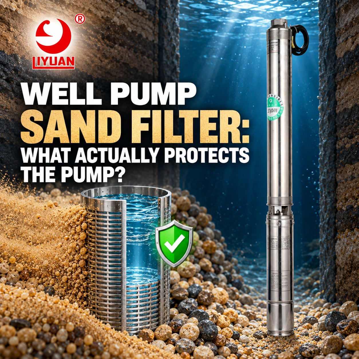
For Wells Containing Abrasive Particles, Consider A Sand Resistant Submersible Pump.
How To Diagnose Submersible Pump Cavitation
Record The Pumping Water Level
Measure The Static Water Level Before Starting.
Then Measure The Dynamic Water Level During Normal operation. Continue Monitoring Until The Level Stabilizes.
Compare The Dynamic Level With The Pump Inlet elevation. This Difference Represents Pump Submergence.
Measure Actual Flow
Use A Suitable Flow Meter Instead Of Estimating Capacity From Pipe Size Or Tank-Filling time.
Compare Measured Flow With The Pump’s Recommended operating range.
Excessive Flow Can Raise NPSHR And Increase Cavitation risk.
Measure Discharge Pressure
Record Pressure At A Known Elevation.
Then Combine Pressure Head, Vertical Lift, Velocity Head, And Friction Loss To Calculate Total Dynamic Head.
A Low System Head May Allow The Pump To Produce Excessive flow.
Check Input Power And Current
Record Voltage, Current, Power Factor, Input Power, And Phase balance.
Cavitation Can Make Electrical load Unstable. However, Current Changes May Remain small.
Electrical Measurements Should Support Hydraulic Tests, Not Replace Them.
Inspect The Pump Inlet
Check The Inlet Screen For Scale, Sand, Debris, Biological Growth, And Mechanical damage.
Also Inspect The Flow Sleeve, Cable Guard, And Nearby Components For Obstructions.
Inspect The First-Stage Impeller
Cavitation Often Begins Near The First-Stage impeller eye.
Look For:
- Localized Pitting
- Rough Surfaces
- Missing Material
- Damaged Blade Edges
- Uneven Erosion
- Cracks
- Distorted Passages
Use The Submersible Pump Impeller: Complete Guide To Evaluate Common Impeller Problems.
Compare Different Operating Conditions
Reduce Flow Gradually With An Approved Discharge Control Method Or Lower The Variable Frequency Drive speed.
If Noise, Vibration, And Pressure Instability Decrease, Excessive Flow Or Insufficient NPSH May Be Contributing To The problem.
Never Restrict The Pump Inlet To Perform This Test.
How To Prevent Submersible Pump Cavitation
Maintain Adequate Submergence
Install The Pump Below The Lowest Expected Dynamic Water level.
Include Seasonal Changes, Drought Conditions, Well Aging, And Peak demand.
Do Not Base Installation Depth Only On A One-Time Static Water-Level measurement.
Match Pump Capacity To Well Yield
The Pump’s Normal Flow Should Not Exceed The Sustainable Well yield.
If Demand Exceeds Instantaneous Well Capacity, Use A Storage Tank. The Pump Can Then Operate At A Lower, Sustainable Rate.
Select The Correct Pump Curve
Choose A Pump That Meets Required Flow And Head Near Its Efficient operating range.
Avoid Selecting A Pump That Must Run Near Maximum flow.
A High Flow Deep Well Pump Must Receive Adequate Water At The Inlet. Otherwise, Its Higher Capacity Can Produce Excessive Drawdown And Cavitation.
Apply A Suitable NPSH Margin
Ensure NPSHA Remains Higher Than NPSHR Under The Worst Expected condition.
Consider:
- Minimum Atmospheric Pressure
- Maximum Site Altitude
- Maximum Water Temperature
- Lowest Pumping Water Level
- Maximum Flow Rate
- Dirty Screen Losses
- Measurement Uncertainty
- Long-Term Well Changes
Consult The Pump Manufacturer When NPSH Margin Is Limited.
Clean The Intake And Well Screen
Remove Deposits Before They Create Severe restrictions.
A Maintenance Program Should Track Changes In Flow, Drawdown, Pressure, And Energy use.
A Rising Drawdown At The Same Flow May Indicate Well-screen blockage Or Aquifer deterioration.
Control Maximum Flow
Use Correct Pump Selection, Discharge Control, Or Variable-Speed Control To Keep Flow Within The Approved range.
Never Throttle The Pump Inlet.
When Throttling Is Required For Testing Or Fixed-Speed Adjustment, Use A Suitable Valve On The Discharge Side.
Control Water-Level Drawdown
Install Low-Water Sensors, Level Probes, Or Well-Recovery controls.
A Variable Frequency Drive Can Reduce Speed When Water level Falls. However, The Minimum Speed Must Remain Compatible With Motor cooling And Pump operation.
Use Suitable Materials
Stainless Steel, Bronze, And Other Cavitation-Resistant Materials Can Delay erosion.
However, Stronger Materials Do Not Correct The Hydraulic Cause.
The System Must Still Provide Adequate Inlet pressure.
Can A Damaged Cavitating Pump Be Repaired?
Minor Cavitation Damage May Allow Continued Operation After The Root Cause Is corrected.
Severe Damage May Require Replacement Of:
- First-Stage Impeller
- Additional Impellers
- Diffusers
- Wear Rings
- Pump Casing
- Radial Bearings
- Thrust Components
- Pump Shaft
- Coupling
Technicians Should Measure Clearances And Compare Every Hydraulic Stage With Manufacturer limits.
Replacing Damaged Parts Without Correcting Water Level, Flow, Or NPSH Conditions Will Cause The Problem To Return.
Frequently Asked Questions
Can A Fully Submerged Pump Cavitate?
Yes. Local Pressure Near The Impeller Eye Can Fall Below Vapor Pressure Even When The Pump Remains Underwater.
Does Lowering A Pump Deeper Prevent Cavitation?
Greater Submergence Can Increase Available Inlet pressure. However, The Pump Must Maintain Safe Clearance From The Well Bottom And Avoid Sediment.
Can Excessive Flow Cause Cavitation?
Yes. High Flow Increases Inlet Velocity And Often Raises NPSHR. It Can Also Increase Well Drawdown.
Does Hot Water Increase Cavitation Risk?
Yes. Hotter Water Has A Higher Vapor pressure. Therefore, The Pump Requires More Inlet Pressure To Prevent Vapor Formation.
Can A Variable Frequency Drive Stop Cavitation?
A Drive Can Reduce Pump Speed And Flow. This Action May Increase NPSH margin And Reduce Drawdown. However, Correct Pump Selection And Inlet Conditions Remain Essential.
Is Cavitation Noise Always Easy To Hear?
No. Deep Installation, Water, Well Casing, And Riser Pipe Can Reduce Or Change The Sound Reaching The surface.
Can Cavitation Damage A Submersible Motor?
Cavitation Mainly Affects Hydraulic Components. However, The Resulting Vibration And Unstable Load Can Increase Stress On The Motor, Bearings, And Coupling.
Is Cavitation The Same As Dry Running?
No. Cavitation Occurs When Vapor Bubbles Form And Collapse Within Flowing liquid. Dry Running Occurs When The Pump Operates Without Enough Water For Cooling And Lubrication.
Conclusion
Submersible Pump Cavitation Develops When Pressure Near The Pump Inlet Or Impeller Falls Below The Water’s Vapor pressure.
Common Causes Include Insufficient Submergence, Excessive Flow, Falling Water Levels, Restricted Inlets, High Water Temperature, And Incorrect Pump selection.
Operators Should Measure Dynamic Water Level, Flow, Pressure, Input Power, And Vibration Before Confirming The cause.
Adequate NPSH Margin, Correct Pump Capacity, Proper Installation Depth, Clean Inlet Screens, And Stable Operating Controls Provide The Best Protection.
Liyuan Pump Can Evaluate Well Diameter, Water Level, Flow, Total Dynamic Head, Water Temperature, Motor Power, And Control Requirements To Develop A Reliable Deep Well Pumping Solution.
Email:Liyuan@liyuan-pump.com
WhatsApp:+86 181-2828-2767