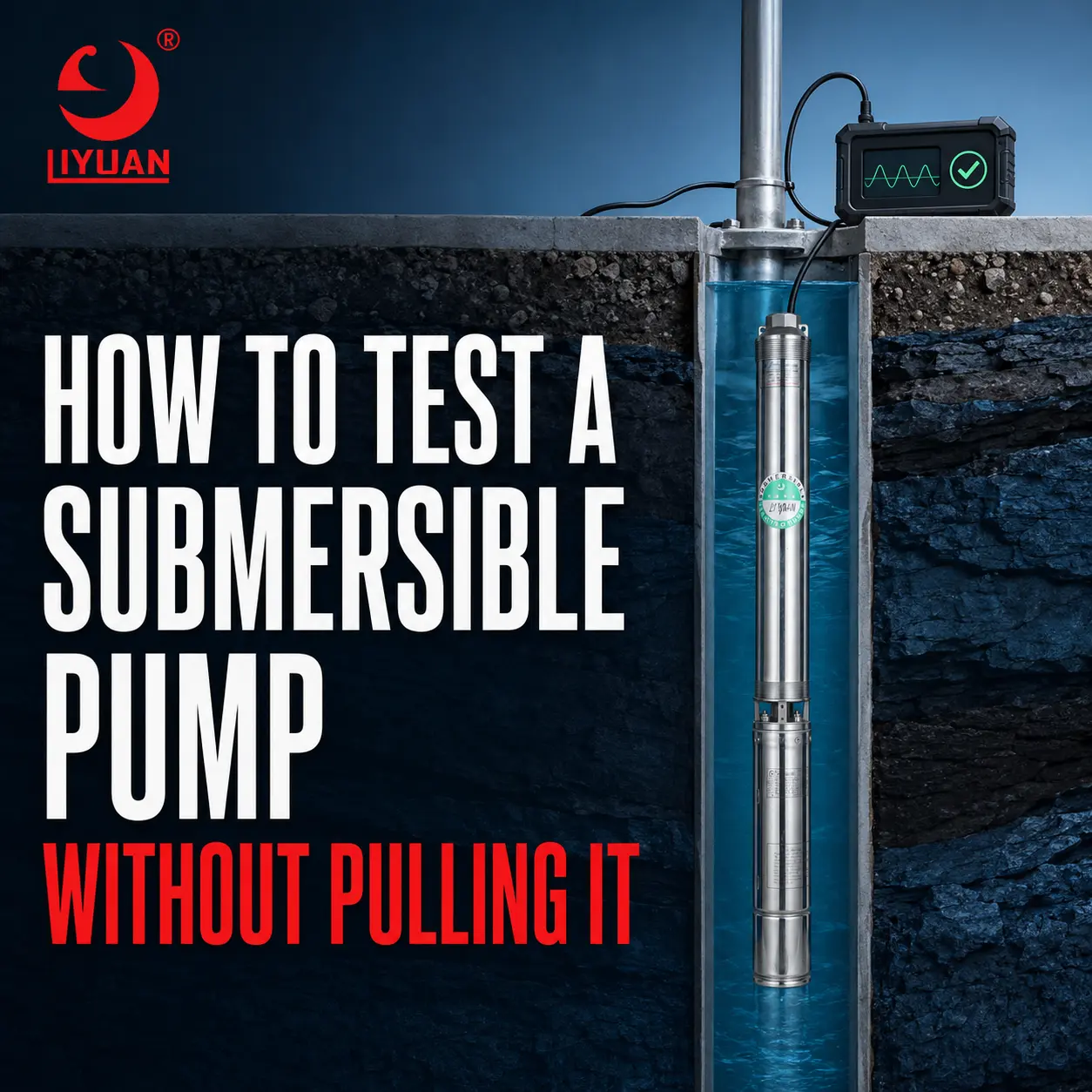
How To Test A Submersible Pump Without Pulling It
You Can Test A Submersible Pump Without Removing It From The Well By Measuring Supply Voltage, Running Current, Winding Resistance, Insulation Resistance, Water Pressure, Flow Rate, And Dynamic Water Level. These Surface Tests Can Identify Most Electrical, Hydraulic, And Control-System Problems Before Expensive Pump Removal Becomes Necessary.
A Deep Well Pump Can Be Difficult And Costly To Remove, Especially When It Is Installed Hundreds Of Feet Below Ground. A Structured Surface Diagnostic Process Helps Determine Whether The Fault Is In The Pump, Submersible Motor, Drop Cable, Control Box, Pressure System, Well, Or Discharge Pipe.
Important Electrical Safety Notice
Submersible Pump Testing May Involve Dangerous Voltage, Stored Capacitor Energy, And Pressurized Water.
Live Electrical Tests Should Be Performed Only By A Qualified Electrician Or Pump Technician Using Properly Rated Instruments And Personal Protective Equipment.
Before Performing Resistance, Continuity, Or Insulation Tests:
- Disconnect And Lock Out The Power Supply.
- Verify Zero Voltage With A Suitable Meter.
- Follow The Pump And Motor Manufacturer’s Wiring Diagram.
- Discharge Control-Box Capacitors According To The Manufacturer’s Procedure.
- Disconnect The Motor Circuit From VFDs, Soft Starters, Controllers, And Sensitive Electronics.
- Never Apply An Insulation-Resistance Test Voltage Through A VFD Or Electronic Controller.
Can A Deep Well Pump Be Fully Tested From The Surface?
A Technician Can Diagnose Many Problems From The Surface, But Not Every Test Can Identify The Exact Failed Component.
Surface Testing Can Usually Determine Whether The Problem Is Related To:
- Incoming Power
- Voltage Drop
- Current Overload
- Phase Imbalance
- Open Motor Windings
- Ground Leakage
- Damaged Drop Cable
- Failed Pressure Switch
- Defective Control Box
- Incorrect VFD Settings
- Low Well Yield
- Excessive Total Dynamic Head
- Restricted Discharge Pipe
- Leaking Check Valve
- Worn Pump Hydraulics
However, The Motor, Underwater Cable Splice, And Drop Cable Form One Connected Electrical Circuit. A Low Insulation-Resistance Reading May Confirm A Downhole Electrical Fault Without Showing Whether The Damage Is In The Motor, Splice, Or Cable.
Pump Removal May Still Be Required To Locate And Repair The Exact Defective Part.
What Tools Are Needed To Test A Submersible Pump?
| Testing Tool | Main Purpose |
|---|---|
| True-RMS Multimeter | Measuring Supply Voltage, Continuity, And Resistance |
| Clamp Ammeter | Measuring Starting And Running Current |
| Insulation-Resistance Tester | Checking Leakage Between Motor Leads And Ground |
| Pressure Gauge | Measuring System And Pump Discharge Pressure |
| Flow Meter Or Timed Container | Checking Actual Pump Flow |
| Water-Level Meter | Measuring Static And Dynamic Water Levels |
| Manufacturer Wiring Diagram | Identifying Motor Leads And Correct Test Points |
| Pump Performance Curve | Comparing Actual Flow And Head With Expected Performance |
| VFD-Compatible Analyzer | Measuring PWM Motor Output When Required |
An Ordinary Multimeter May Produce Inaccurate Readings On The Output Side Of A Variable Frequency Drive. Use The Drive’s Diagnostic Data Or A Meter Specifically Designed For PWM Waveforms.
Quick Submersible Pump Diagnostic Table
| Pump Symptom | First Tests To Perform | Possible Causes |
|---|---|---|
| Pump Does Not Start | Control Signal, Voltage, Continuity, Winding Resistance | Open Circuit, Failed Switch, Faulty Contactor, Broken Cable, Open Winding |
| Pump Hums But Does Not Start | Loaded Voltage, Starting Current, Capacitor, Control Box | Low Voltage, Failed Capacitor, Locked Rotor, Incorrect Wiring |
| Breaker Trips Immediately | Insulation Resistance, Winding Resistance, Cable Inspection | Short Circuit, Ground Fault, Damaged Cable, Burned Motor |
| Overload Trips After Running | Running Current, Voltage, Flow, Water Level | Overload, Voltage Drop, Blockage, Motor Cooling Problem |
| Low Water Pressure | Pressure, Flow, Dynamic Water Level, Current | Worn Impellers, Pipe Leak, Low Well Yield, Excessive Head |
| Pump Starts Too Frequently | Pressure Switch, Tank, Check Valve, Pipe Leakage | Waterlogged Tank, Leaking Valve, Incorrect Pressure Setting |
| Pump Runs But Delivers No Water | Water Level, Current, Valve Position, Pipe Pressure | Dry Well, Broken Pipe, Closed Valve, Failed Coupling |
| Three-Phase Current Is Unequal | Phase Voltage, Phase Current, Terminals | Supply Imbalance, Loose Connection, Cable Fault, Winding Damage |
Step 1: Record The Pump And Installation Data
Begin With The Motor Nameplate, Pump Model, Installation Record, And Control-System Information.
Record The Following Data:
- Pump Model And Serial Number
- Motor Power In HP Or kW
- Rated Voltage
- Rated Current
- Single-Phase Or Three-Phase Supply
- Two-Wire Or Three-Wire Motor
- Rated Frequency
- Pump Setting Depth
- Drop-Cable Size And Length
- Discharge-Pipe Diameter
- Static Water Level
- Previous Dynamic Water Level
- Original Flow And Pressure
- Control-Box Or VFD Model
- Pump Installation Date
These Reference Values Make The Test Results More Meaningful. A Current Reading Without The Motor Nameplate Current, For Example, Cannot Confirm Whether The Motor Is Operating Normally.
The Franklin Electric AIM Resources Provide Application, Installation, And Maintenance Information For Submersible Motors. Always Prioritize The Manual For The Exact Motor And Control System Being Tested.
Step 2: Check The Pump Controller And Start Command
Confirm That The Pump Is Actually Receiving A Start Command.
Inspect The:
- Main Disconnect
- Circuit Breaker
- Fuses
- Pressure Switch
- Float Switch
- Level Controller
- Contactor
- Overload Relay
- Control Transformer
- VFD Fault History
- Dry-Run Protection Device
- Remote Start Signal
A Pump That Does Not Run May Have A Perfectly Functional Motor But A Failed Control Device.
Inspect The Submersible Pump Pressure Switch For Burned Contacts, Blocked Pressure Ports, Loose Terminals, And Incorrect Cut-In Or Cut-Out Settings.
For A Three-Wire Single-Phase Motor, Inspect The Electric Control Box For Submersible Pump. A Failed Start Capacitor, Run Capacitor, Relay, Or Contactor Can Prevent The Motor From Starting Even When The Downhole Pump Is Undamaged.
Step 3: Measure The Supply Voltage
Measure The Incoming Voltage Before Starting The Pump. Then Measure It Again While The Motor Is Starting And Running.
A Voltage Reading That Appears Normal With The Pump Off May Drop Excessively Under Load. This Can Result From:
- Undersized Supply Conductors
- Excessive Cable Length
- Loose Terminals
- Burned Contactor Contacts
- Weak Utility Supply
- Generator Voltage Instability
- Incorrect Transformer Capacity
- Damaged Drop Cable
- Poor Cable Splices
Compare The Results With The Motor Manufacturer’s Permitted Voltage Range. Do Not Assume That One Universal Voltage Tolerance Applies To Every Motor.
Voltage Should Be Checked At The Input And Output Of The Relevant Control Equipment. This Helps Identify Where The Voltage Loss Occurs.
Proper Submersible Pump Voltage Protection Can Disconnect The Motor During Undervoltage, Overvoltage, Phase Loss, Or Severe Voltage Imbalance.
Step 4: Measure Starting And Running Current
Use A Clamp Ammeter To Measure The Current In Each Motor Conductor.
Compare The Measurements With:
- Motor Nameplate Current
- Manufacturer Performance Data
- Original Commissioning Records
- Current Readings From Previous Inspections
Current Patterns Can Reveal Different Pump Conditions.
| Current Pattern | Likely Interpretation |
|---|---|
| Zero Current After A Confirmed Start Command | Open Circuit, Open Contactor, Broken Cable, Or No Controller Output |
| High Current With No Motor Acceleration | Locked Rotor, Low Voltage, Incorrect Wiring, Or Failed Starting Circuit |
| High Balanced Running Current | Hydraulic Overload, Mechanical Drag, Incorrect Duty Point, Or Motor Overload |
| Unequal Three-Phase Current | Supply Imbalance, Loose Connection, Cable Damage, Or Winding Problem |
| Low Current With Low Flow | Dry Running, Broken Pipe, Failed Coupling, Or Insufficient Pump Load |
| Normal Current With Low Pressure | Worn Pump Stages, Discharge Leak, Incorrect Pump Selection, Or Excessive Head |
| Current Fluctuation | Unstable Water Level, Cavitation, Loose Connection, Or Variable Hydraulic Load |
Do Not Repeatedly Start A Motor That Hums, Stalls, Or Draws Locked-Rotor Current. Repeated Starting Can Rapidly Overheat The Windings And Damage The Starting Components.
Step 5: Calculate Three-Phase Current Imbalance
For A Three-Phase Submersible Motor, Measure The Current In All Three Phases.
Use This Formula:
Current Imbalance (%) = Maximum Deviation From Average Current ÷ Average Current × 100
For Example, Assume The Measured Currents Are:
- Phase A: 9.6 A
- Phase B: 10.0 A
- Phase C: 10.4 A
The Average Current Is:
Average Current = (9.6 + 10.0 + 10.4) ÷ 3 = 10.0 A
The Maximum Deviation From The Average Is 0.4 A.
Therefore:
Current Imbalance = 0.4 ÷ 10.0 × 100 = 4%
Compare The Result With The Motor Manufacturer’s Maximum Permitted Imbalance. Excessive Imbalance Can Overheat The Motor Even When The Average Current Is Below The Nameplate Rating.
The Grundfos Motor-Protection Recommendations Also Emphasize That The Maximum Protection Setting Should Not Exceed The Maximum Motor Current Stamped On The Rating Plate.
Step 6: Measure Winding Resistance
Winding-Resistance Testing Must Be Performed With The Power Disconnected And The Motor Leads Isolated From The Controller.
Measure Resistance Between The Motor Leads According To The Manufacturer’s Wiring Diagram.
For A Three-Phase Motor, The Three Phase-To-Phase Measurements Should Normally Be Closely Balanced. A Significant Difference Can Indicate:
- Damaged Motor Windings
- Loose Connections
- Corroded Terminals
- Partially Broken Conductors
- Defective Cable Splices
- Measurement Errors
For A Single-Phase Three-Wire Motor, The Start And Run Windings Have Different Resistance Values. Lead Identification And Expected Relationships Must Follow The Correct Motor Diagram.
Remember That A Surface Measurement Includes The Resistance Of The Motor Windings, Drop Cable, And Connections. Long Or Small-Gauge Cables Can Add Noticeable Resistance.
Copper Resistance Also Changes With Temperature. Compare Measurements Under Similar Conditions Whenever Possible.
Step 7: Test Insulation Resistance To Ground
An Insulation-Resistance Test Checks Whether Current Can Leak From The Motor Circuit To Ground.
After Disconnecting The Motor Circuit From All Electronic Equipment, Test Each Motor Lead To The Ground Conductor Or Well Casing, Following The Manufacturer’s Procedure.
Possible Causes Of Low Insulation Resistance Include:
- Water Entering A Cable Splice
- Damaged Submersible Pump Cable
- Cracked Cable Insulation
- Motor-Winding Deterioration
- Moisture In A Terminal Box
- Contaminated Connections
- Lightning Or Surge Damage
Use The Test Voltage Specified By The Motor Manufacturer. Do Not Apply A High Test Voltage Based On A Generic Online Recommendation.
One Insulation Reading Should Not Be Evaluated In Isolation. Cable Length, Motor Temperature, Moisture, Test Voltage, And Previous Results All Affect Interpretation. A Declining Trend Is Often More Useful Than A Single Measurement.
A Surface Insulation Test Usually Confirms That A Ground Fault Exists Somewhere In The Downhole Circuit. It May Not Distinguish Between The Motor, Drop Cable, And Underwater Splice Until The Equipment Is Separated.
Step 8: Measure Pump Pressure And Flow Rate
Electrical Tests Alone Cannot Confirm Hydraulic Performance.
Measure The Actual Discharge Pressure And Water Flow While The Pump Is Operating. Compare The Results With The Pump Curve And Original Installation Data.
A Practical Flow Test Can Be Performed With A Calibrated Flow Meter Or A Container Of Known Volume.
Use This Formula:
Flow Rate = Collected Water Volume ÷ Filling Time
For Example, If A 200-Liter Tank Fills In 40 Seconds:
Flow Rate = 200 ÷ 40 = 5 Liters Per Second
This Equals:
5 × 60 = 300 Liters Per Minute
Review The Submersible Pump Flow Rate Requirements Before Concluding That The Pump Is Undersized.
Low Flow Can Be Caused By:
- Falling Well Water Level
- Clogged Pump Inlet
- Worn Impellers Or Diffusers
- Sand Damage
- Restricted Pipework
- Partially Closed Valve
- Excessive Discharge Pressure
- Incorrect Pump Rotation
- Broken Riser Pipe
- Leaking Check Valve
- Incorrect Pump Selection
Step 9: Check Static And Dynamic Water Levels
The Static Water Level Is The Water Level When The Pump Is Off And The Well Has Recovered.
The Dynamic Water Level Is The Water Level While The Pump Is Operating.
The Difference Between These Levels Is The Drawdown:
Drawdown = Dynamic Water Level − Static Water Level
A Rapidly Falling Dynamic Water Level May Indicate That The Pump Capacity Exceeds The Well’s Sustainable Yield.
Common Signs Of Excessive Drawdown Include:
- Air Mixed With The Discharge Water
- Unstable Flow
- Changing Motor Current
- Rapid Pressure Fluctuation
- Dry-Run Protection Trips
- Pump Performance Declining During Extended Operation
- Flow Recovering After The Pump Rests
If Water Level Is The Problem, Pulling And Replacing The Pump May Not Solve It. The Correct Solution Could Be A Lower Flow Rate, Deeper Pump Setting, Storage Tank, Variable-Speed Control, Or Well Rehabilitation.
Step 10: Calculate The Actual Total Dynamic Head
Total Dynamic Head Determines The Hydraulic Load Against Which The Pump Operates.
A Simplified Calculation Is:
TDH = Vertical Lift + Required Discharge Pressure Head + Pipe Friction Losses
For Water:
Pressure Head In Meters ≈ Pressure In Bar × 10.2
For Example, A System With A 60-Meter Vertical Lift, 3 Bar Required Pressure, And 8 Meters Of Friction Loss Has An Approximate TDH Of:
TDH = 60 + (3 × 10.2) + 8
TDH = 98.6 Meters
Compare The Calculated Duty Point With The Manufacturer’s Pump Curve. A Pump Operating Far From Its Recommended Range May Produce Low Flow, Excessive Current, Vibration, Thrust-Bearing Stress, Or Poor Efficiency.
Use The Total Dynamic Head For Submersible Pump Calculation Method When Selecting Or Troubleshooting A Deep Well Pump.
How Can You Check For A Leaking Pipe Or Check Valve?
Run The Pump Until The System Reaches Its Normal Shut-Off Pressure. Stop The Pump And Observe The Pressure Gauge.
A Rapid Pressure Drop Without Water Demand May Indicate:
- A Leaking Check Valve
- A Broken Riser Pipe
- A Leaking Underground Pipe
- A Faulty Foot Valve In An Applicable System
- A Pressure-Tank Problem
- An Open Outlet
- Leakage Back Into The Well
A Faulty Submersible Pump Check Valve Can Cause Reverse Flow, Frequent Cycling, Delayed Pressure, And Water Hammer.
Pressure Loss Alone Does Not Identify The Exact Leak location. Isolate Accessible Sections Of The System Where Possible Before Deciding To Pull The Pump.
How Can You Tell Whether The Pump Or Control Box Is Bad?
A Control-Box Problem Is More Likely When:
- The Supply Voltage Is Correct
- The Motor Circuit Has Reasonable Resistance
- Insulation Resistance Is Acceptable
- The Contactor Does Not Close
- A Start Capacitor Is Swollen Or Open
- A Relay Does Not Transfer Correctly
- The Controller Shows An Internal Fault
- Output Voltage Is Missing
A Downhole Motor Or Cable Problem Is More Likely When:
- The Motor Circuit Is Open
- Insulation Resistance Is Abnormally Low
- Winding Resistance Is Severely Unbalanced
- The Breaker Trips With The Downhole Circuit Connected
- Starting Current Remains Extremely High
- The Motor Cannot Accelerate Despite Correct Voltage And Starting Components
Replace Control Components Only After Confirming Their Ratings And Compatibility With The Motor.
How Can You Tell Whether The Pump Is Running Dry?
Possible Dry-Running Indicators Include:
- Very Low Or Zero Water Flow
- Falling Dynamic Water Level
- Lower-Than-Normal Motor Current
- Unstable Current
- Air In The Discharge Water
- Dry-Run Alarm
- Flow Returning After The Well Recovers
Do Not Continue Operating The Pump To Confirm A Dry-Well Condition. Insufficient Water Can Reduce Motor Cooling And Damage Pump Components.
When Should A Submersible Pump Be Pulled?
Pump Removal Is Usually Justified When Testing Indicates:
- A Confirmed Downhole Ground Fault
- An Open Motor Or Drop-Cable Circuit
- A Locked Rotor
- A Broken Riser Pipe
- A Failed Pump-To-Motor Coupling
- Severe Pump-Stage Wear
- Persistent Low Performance After External Restrictions Are Eliminated
- Repeated Mechanical Noise Or Vibration
- Downhole Cable Damage
- Motor Failure Confirmed By Electrical Measurements
The Pump Should Not Be Pulled Until Accessible Components Have Been Checked. Pressure Switches, Control Boxes, VFD Settings, Valves, Filters, Pressure Tanks, And Surface Wiring Are Usually Faster And Less Expensive To Repair.
What Information Should Be Sent To The Pump Manufacturer?
Accurate Operating Data Helps A Manufacturer Recommend The Correct Solution.
Provide:
- Pump Model
- Motor Model
- Rated Voltage And Current
- Power Rating
- Frequency
- Phase
- Pump Setting Depth
- Well Diameter
- Drop-Cable Size And Length
- Static Water Level
- Dynamic Water Level
- Measured Flow Rate
- Measured Discharge Pressure
- Voltage Before And During Operation
- Current In Every Conductor
- Winding-Resistance Results
- Insulation-Resistance Results
- Controller Fault Codes
- Pipe Diameter And Length
- Number Of Starts Per Hour
- Water Temperature
- Sand Content
- Installation Date
- Description Of The Original And Current Performance
Photos Of The Nameplate, Control Panel, Wiring Connections, And Pressure Gauge Can Also Improve Remote Diagnosis.
Frequently Asked Questions
Can You Test A Submersible Pump With A Multimeter?
Yes. A Multimeter Can Measure Supply Voltage, Continuity, And Winding Resistance. However, It Cannot Measure Water Flow, Dynamic Water Level, Pump Head, Or Insulation Resistance At A Suitable Test Voltage. A Complete Diagnosis Usually Requires Several Instruments.
Can You Test A Well Pump Without Removing It?
Yes. Voltage, Current, Resistance, Insulation, Pressure, Flow, Water Level, And Controller Data Can All Be Checked From The Surface. These Tests Often Show Whether Pump Removal Is Necessary.
What Does Infinite Resistance Mean On A Pump Motor?
Infinite Resistance Between The Correct Motor Leads Usually Indicates An Open Circuit. The Cause Could Be A Broken Drop Cable, Failed Splice, Loose Connection, Thermal Protector, Or Open Motor Winding.
What Does Low Resistance To Ground Mean?
Low Resistance From A Motor Lead To Ground Suggests Insulation Leakage. The Fault May Be In The Drop Cable, Underwater Splice, Motor Lead, Or Motor Winding.
Why Does A Submersible Pump Draw High Amps?
Common Causes Include Low Voltage, A Locked Rotor, Mechanical Drag, Incorrect Pump Selection, Excessive Flow, Sand Accumulation, Motor Damage, Or A Faulty Single-Phase Starting Circuit.
Why Does A Submersible Pump Draw Low Amps?
Low Current May Indicate Dry Running, Low Hydraulic Load, A Broken Discharge Pipe, A Failed Coupling, Incorrect Rotation, Or Severely Worn Pump Components.
Can A Pressure Test Confirm A Bad Pump?
Pressure Testing Can Confirm Poor System Performance, But It Cannot Identify The Pump As The Cause By Itself. Low Pressure Can Also Result From Low Water Level, Pipe Leakage, A Restricted Inlet, An Open Valve, Or Excessive Total Dynamic Head.
Should A VFD-Driven Pump Be Tested At The Motor Terminals?
Only With Instruments And Procedures Approved For VFD Output. Pulse-Width-Modulated Voltage Can Produce Misleading Readings On An Ordinary Meter. Review The VFD Fault History, Input Supply, Output Current, Frequency, And Manufacturer Diagnostics First.
Can A Bad Pressure Tank Make The Pump Look Faulty?
Yes. An Incorrect Precharge, Ruptured Bladder, Or Waterlogged Tank Can Cause Rapid Cycling, Pressure Fluctuation, And Motor Overheating Even When The Pump Is Still Functional.
How Often Should Pump Test Results Be Recorded?
Record Baseline Data During Commissioning And Repeat The Measurements During Scheduled Maintenance. Trending Voltage, Current, Flow, Pressure, Insulation Resistance, And Water Level Can Reveal Deterioration Before Complete Failure Occurs.
Final Answer
The Best Way To Test A Submersible Pump Without Pulling It Is To Combine Electrical And Hydraulic Measurements. Check The Control Signal, Loaded Voltage, Running Current, Winding Resistance, Insulation Resistance, Flow Rate, Pressure, Dynamic Water Level, And Total Dynamic Head.
No Single Measurement Can Diagnose Every Deep Well Pump Problem. Compare All Results With The Motor Nameplate, Pump Curve, Manufacturer’s Manual, And Original Commissioning Data.
If You Are Selecting A Replacement Deep Well Pump Or Need Help Interpreting Test Results, Send Liyuan Pump Your Well Depth, Water Level, Required Flow, Required Pressure, Voltage, Frequency, Pipe Size, And Test Measurements. This Information Allows Our Engineering Team To Recommend A Reliable Pump And Motor Combination For Your Application.
Email:Liyuan@liyuan-pump.com
WhatsApp:+86 181-2828-2767