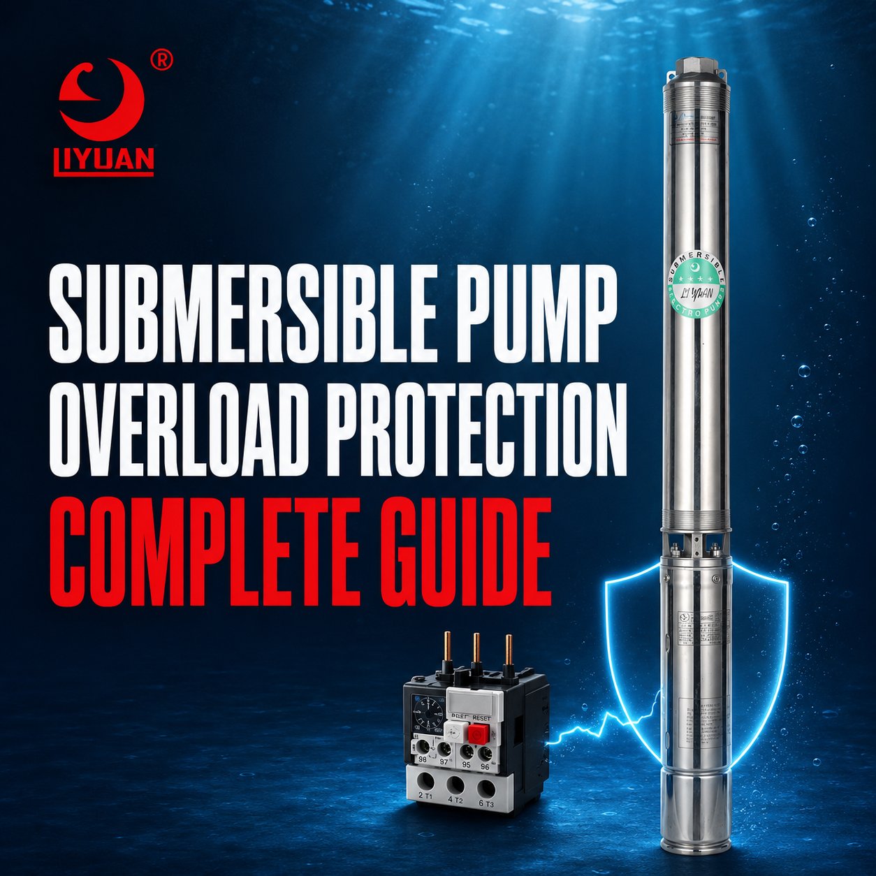
Submersible Pump Overload Protection Prevents Motor Damage By Detecting Abnormal Current, Excessive Heat, Phase Failure, Locked Rotor Conditions, And Other Electrical Or Mechanical Problems.
When A Dangerous Condition Occurs, The Protection System Disconnects The Motor Before The Windings, Cables, Bearings, Or Control Components Suffer Permanent Damage.
The Correct Protection System Should Include More Than A Standard Circuit Breaker. Depending On The Application, It May Require A Thermal Overload Relay, Electronic Motor Protector, Phase Monitor, Temperature Sensor, Control Box, Or Variable Frequency Drive.
Correct Settings Are Equally Important. An Overload Device Set Too Low Can Cause Nuisance Trips. However, A Device Set Too High May Allow The Motor To Overheat Until The Winding Insulation Fails.
This Guide Explains How Pump Overloads Develop, How Different Protection Devices Work, And How To Select The Correct Protection Solution For A Deep Well Pump System.
What Is Submersible Pump Overload Protection?
Submersible Pump Overload Protection Is An Electrical And Thermal Safety System Designed To Protect A Pump Motor From Operating Above Its Safe Load.
Every Motor Has A Rated Current Shown On Its Nameplate. Under Normal Conditions, The Motor Should Operate Within The Current, Voltage, Temperature, And Starting Limits Specified By The Manufacturer.
If The Motor Draws Excessive Current For Too Long, Electrical Energy Converts Into Additional Heat Inside The Windings. This Heat Accelerates Insulation Aging And Can Eventually cause A Short Circuit Or Winding Failure.
An Overload Protector Monitors Motor Operating Conditions And Stops The Motor When Those Conditions Become Unsafe.
Modern Protection Systems Can Monitor:
- Motor Current
- Supply Voltage
- Phase Loss
- Phase Imbalance
- Locked Rotor Conditions
- Excessive Starting Frequency
- Motor Temperature
- Ground Faults
- Underload Conditions
- Dry Running
- Pump Stall Conditions
The Required Protection Functions Depend On The Motor Type, Pump Power, Supply System, Cable Length, Well Depth, And Operating Environment.
Why Is Overload Protection Important?
A Submersible Motor Operates Deep Inside A Well, Borehole, Tank, Or Reservoir. Unlike A Surface Motor, It Cannot Be Inspected Easily During Operation.
A Small Electrical Problem Can Continue Undetected Until The Pump Stops Completely. Removing A Failed Deep Well Pump May Require Lifting Equipment, Skilled Technicians, And Considerable Labor.
Effective Overload Protection Helps Prevent:
- Burned Motor Windings
- Damaged Winding Insulation
- Melted Power Cables
- Failed Cable Connections
- Damaged Capacitors
- Worn Bearings
- Shaft And Coupling Damage
- Contactor Failure
- Unexpected Pump Downtime
- Expensive Pump Removal
Protection Is Particularly Important For High-Power Deep Well Submersible Motors Used In Agricultural, Municipal, Commercial, And Industrial Water Systems.
Overload Protection Vs. Short-Circuit Protection
Overload Protection And Short-Circuit Protection Perform Different Functions.
| Protection Type | Main Purpose | Typical Device |
|---|---|---|
| Overload Protection | Protects Against Sustained Excessive Motor Current | Thermal Or Electronic Overload Relay |
| Short-Circuit Protection | Interrupts Extremely High Fault Current | Fuse Or Circuit Breaker |
| Ground-Fault Protection | Detects Current Leaking To Ground | Ground-Fault Relay Or Breaker |
| Phase Protection | Detects Phase Loss, Reversal, Or Imbalance | Phase Monitoring Relay |
| Dry-Run Protection | Detects Insufficient Water Or Abnormally Low Motor Load | Level Sensor Or Electronic Pump Protector |
| Temperature Protection | Detects Excessive Motor Or Winding Temperature | PTC, PT100, Or Thermal Switch |
A Circuit Breaker Should Not Automatically Be Considered A Replacement For A Motor Overload Relay.
A Breaker Primarily Protects The Circuit From Short Circuits And Very High Fault Current. A Motor Can Operate At A Moderate But Damaging Overload For An Extended Period Without Immediately Tripping A Standard Breaker.
The Pump Installation Should Therefore Use Coordinated Short-Circuit, Overload, Ground-Fault, And Phase Protection.
Common Causes Of Submersible Pump Overload
Incorrect Pump And Motor Matching
The Motor Must Have Enough Power To Drive The Pump At Every Expected Operating Point.
If The Pump Requires More Shaft Power Than The Motor Can Provide, The Motor Will Draw Excessive Current. This Problem May Occur When A Large Pump End Is Connected To An Undersized Motor.
Always Compare The Pump Power Curve With The Motor Rating before Installation.
Excessive Pump Flow
A Centrifugal Pump Can Require More Motor Power As Flow Increases, Depending On Its Hydraulic Design.
If The Pump Operates Too Far To The Right Of Its Recommended Performance Range, The Motor May Draw More Current Than Its Rated Value.
This Condition Can Result From:
- Insufficient System Resistance
- Incorrect Pump Selection
- A Discharge Valve Opened Beyond The Design Condition
- A Lower Actual Head Than Expected
- An Oversized Pump
- An Incorrect Impeller Or Stage Configuration
Selecting An Appropriate High Flow Deep Well Pump Requires Reviewing Both Hydraulic Performance And Motor Power Across The Complete Operating Range.
Low Supply Voltage
Low Voltage Can Prevent A Motor From Producing The Torque Required To Drive The Pump.
The Motor May Then Draw Higher Current, Start Slowly, Or Stall. Long Power Cables, Undersized Conductors, Weak Transformers, Loose Connections, And Unstable Generators Can All Cause Voltage Drop.
Voltage Should Be Measured At The Motor Supply While The Pump Is Operating, Not Only When The System Is Idle.
Excessive Supply Voltage
Voltage Above The Motor Rating Can Also Increase Heating And Electrical Stress.
The Motor And Control Equipment Must Match The Available Supply Voltage. Transformer Taps, Generator Settings, And VFD Output Parameters Should Be Checked When Abnormal Voltage Is Detected.
Phase Loss
Phase Loss Occurs When One Phase Of A Three-Phase Power Supply Is Disconnected.
Possible Causes Include:
- A Blown Fuse
- A Failed Contactor
- A Loose Terminal
- A Broken Cable
- A Damaged Transformer Connection
- A Faulty Control Component
A Running Motor May Continue Operating On The Remaining Phases While Drawing Dangerous Current. This Condition Is Commonly Called Single Phasing.
A Phase-Loss Relay Or Electronic Motor Protector Should Disconnect The Motor Quickly.
Voltage And Current Imbalance
Small Voltage Differences Between Phases Can Produce Much Larger Differences In Motor Current.
Current Imbalance Creates Uneven Winding Temperatures. One Winding Section May Overheat Even When The Average Motor Current Appears Acceptable.
Technicians Should Measure All Three Line-To-Line Voltages And All Three Phase Currents. The Results Should Be Compared With The Motor Manufacturer’s Limits.
Locked Rotor Or Jammed Pump
A Locked Rotor Condition Occurs When The Motor Cannot Turn While Electrical power Remains Applied.
Potential Causes Include:
- Sand Inside The Pump
- A Seized Bearing
- A Bent Shaft
- A Jammed Impeller
- Mineral Scale
- Foreign Material
- A Damaged Coupling
- Incorrect Mechanical Assembly
- Internal Corrosion
Locked-Rotor Current Can Be Several Times Higher Than Normal Operating Current. The Protection Device Must Disconnect The Motor Before The Windings Overheat.
Water Sources Containing Abrasive Particles May Require A Sand Resistant Submersible Pump And Appropriate Filtration Or Well Development.
Bearing Or Shaft Problems
Worn Bearings Increase Mechanical Resistance And Motor Load.
A Misaligned Shaft, Damaged Coupling, Or Tight Bearing Can gradually Increase Current Until The Overload Device Trips.
Repeated Tripping Should Never Be Solved By Simply Raising The Overload Setting. The Pump And Motor Should Be Inspected For Mechanical Resistance.
Frequent Starting
Every Motor Start Produces High Current And Additional Heat.
Frequent Starts May Not Allow The Motor To Cool Between Operating Cycles. This Can Trigger An Overload Or Cycle-Fault Protection Device.
Common Causes Of Excessive Cycling Include:
- A Waterlogged Pressure Tank
- Incorrect Pressure Switch Settings
- A Leaking Check Valve
- A Small Pressure Tank
- Rapidly Changing Water Demand
- Incorrect Level-Control Settings
- A Faulty Sensor
Start Frequency Should Remain Within The Pump And Motor Manufacturer’s Limits.
Insufficient Motor Cooling
Most Submersible Motors Depend On Water Flow Around The Motor Housing For Cooling.
If Water Velocity Is Too Low, Heat Can Accumulate Inside The Motor. This Problem May Occur In A Large-Diameter Well, Tank, Reservoir, Or Open-Water Installation.
A Cooling Sleeve Or Flow Inducer May Be Required To Direct Water Across The Motor surface.
High Water Temperature
Warm Water reduces The Motor’s Ability To Transfer Heat Into The Surrounding Liquid.
Standard Equipment May Need Derating When It Operates Above Its Approved Temperature range. High-Temperature Applications may require A Purpose-Designed Hot Water Submersible Pump.
Incorrect VFD Settings
A Variable Frequency Drive Can Provide Excellent Motor Control, But Incorrect Parameters May Create Overload Problems.
Potential Issues Include:
- Incorrect Motor Rated Current
- Incorrect Motor Voltage
- Excessive Maximum Frequency
- Acceleration Time That Is Too Short
- Inadequate Current Limiting
- An Incorrect Motor Thermal Model
- Continuous Operation Below The Safe Cooling Speed
- Excessive Cable Length Without Output Protection
Every VFD Should Be Configured According To The Motor Nameplate, Pump Curve, Cable Length, And Manufacturer’s Instructions.
What Components Can An Overload Damage?
An Overload Usually Affects More Than The Motor Windings.
Motor Windings
Excessive Current Produces Heat Inside The Copper Windings. Prolonged Heat Weakens The insulation Until Turn-To-Turn Or Phase-To-Phase Failure Occurs.
Power Cable
An Undersized Or Damaged Cable Can Overheat Under High Current. Cable Splices And Terminations Are Especially Vulnerable When Connections Are Loose Or Poorly Sealed.
Contactors
Frequent Starting And High Current Can Damage Contactor Contacts. Burned Contacts Increase Resistance, Which Creates Additional Voltage Drop And Heat.
Capacitors
Single-Phase Motors Often Use Start And Run Capacitors. Incorrect Capacitor Values Or Failed Starting Components Can Prevent Proper Acceleration And Cause High Current.
Bearings
Overheating And Mechanical Overload Can Reduce Bearing Lubrication Performance. Excessive Shaft Load Can Also Damage Radial And Thrust Bearings.
Mechanical Seals And Couplings
A Stalled Or Misaligned Pump Can damage Couplings, Seals, Shafts, And Impellers. The Electrical Trip May therefore indicate A Mechanical Problem rather Than An Electrical Defect.
Main Types Of Submersible Pump Overload Protection
Thermal Overload Relay
A Thermal Overload Relay Uses Heat Produced By Motor Current To Simulate Motor Temperature.
When Current Remains Above The Selected Level, The Relay Opens The Motor Control Circuit. Higher Current Causes A Faster Trip.
This Inverse-Time Characteristic Allows Normal Starting Current While Protecting The Motor From A Sustained Overload.
Thermal Relays Are Simple And Cost-Effective. However, They May Offer Limited Protection Against Phase Imbalance, Dry Running, Ground Faults, Or Excessive Cycling.
Electronic Overload Relay
An Electronic Overload Relay Measures Motor Current With Internal Sensors Or External Current Transformers.
It Can Provide More Accurate And Flexible Protection Than A Basic Thermal Relay.
Depending On The Model, It May Detect:
- Overcurrent
- Undercurrent
- Locked Rotor
- Phase Loss
- Phase Imbalance
- Excessive Starts
- Ground Faults
- High Or Low Voltage
- Dry Running
- Excessive Motor Temperature
Electronic Protectors Can Also Display Operating Data And Store Fault Records, Making Troubleshooting Easier.
For Example, The Franklin Electric SSP SmartStart Pump Starter Includes Electronic Overload, Phase-Imbalance, Locked-Rotor, Stall, Cycle, And Underload Protection.
Phase Monitoring Relay
A Phase Monitoring Relay Protects Three-Phase Motors From:
- Phase Loss
- Phase Reversal
- Low Voltage
- High Voltage
- Voltage Imbalance
- Incorrect Phase Sequence
Phase Reversal Is Particularly Important During Installation. Incorrect Rotation Can Reduce Pump Performance And May Damage Some Pump Assemblies.
Motor Temperature Sensors
Large Or High-Value Motors May Include Embedded Temperature Sensors.
Common Sensor Types Include:
- PTC Thermistors
- PT100 Resistance Sensors
- PT1000 Resistance Sensors
- Bimetal Thermal Switches
These Sensors Measure Actual Motor Or Winding Temperature instead Of Estimating Temperature From Current Alone.
Temperature Monitoring Is Valuable For Hot Water, Poor Cooling, Variable-Speed, And High-Power Applications.
Variable Frequency Drive
A VFD Can Combine Speed Control With Multiple Motor Protection Functions.
Depending On The Drive, It May Provide:
- Electronic Overload Protection
- Current Limiting
- Phase-Loss Detection
- Underload Detection
- Ground-Fault Detection
- Motor Thermal Modeling
- Stall Prevention
- Overvoltage And Undervoltage Protection
- Fault History
However, A VFD Must Be Programmed Correctly. The Presence Of A Drive Does Not Guarantee That Every Protection Function Is Enabled.
Submersible Pump Control Box
A Submersible Pump Control Box Can Contain Contactors, Capacitors, Relays, Circuit Breakers, Overload Devices, And Monitoring Components.
Single-Phase Pump Control Boxes Commonly Include Start And Run Components. Three-Phase Panels May Include Phase Monitoring, Electronic Overload Relays, And Automatic Control Functions.
The Control Box Must Match The Motor’s Power, Voltage, Phase, Starting Method, And Full-Load Current.
How Does A Thermal Overload Relay Work?
A Thermal Overload Relay Does Not Usually Trip Immediately At A Small Overload.
Instead, Its Trip Time Changes According To The Amount Of Excess Current:
- A Small Overload Produces A Relatively Slow Trip
- A Larger Overload Produces A Faster Trip
- A Locked Rotor Produces A Very Fast Temperature Rise
- Normal Starting Current Is Allowed For A Limited Time
This Behavior Represents The Motor’s Heating Pattern More Accurately Than A Simple Instantaneous Current Switch.
After A Trip, The Relay May Require Manual Or Automatic Reset. Manual Reset Is Often Safer Because It Forces An Operator To Investigate The Cause.
Repeated Automatic Restarting Can Expose The Motor To Multiple High-Current Starts And Create A Safety Hazard.
How Should The Overload Relay Be Set?
The Correct Setting Should Be Based On The Motor Nameplate, Manufacturer’s Instructions, Applicable Electrical Standards, Service Factor, Ambient Conditions, And Starting Method.
Technicians Should Verify:
- Motor Rated Current
- Motor Voltage And Phase
- Service Factor
- Current Transformer Ratio
- Relay Connection Method
- Trip Class
- Ambient Temperature Compensation
- Starting Time
- Maximum Starts Per Hour
- VFD Or Soft-Starter Configuration
Never Increase The Setting Merely To Prevent Nuisance Trips.
If A Correctly Selected Relay Trips Repeatedly, The System Has An Electrical, Hydraulic, Or Mechanical Problem That Requires Investigation.
What Is Overload Trip Class?
Trip Class Describes The Approximate Time An Overload Device Allows A Specified High-Current Condition Before Tripping.
Common Classes Include:
- Class 5
- Class 10
- Class 20
- Class 30
A Lower Class Generally Provides Faster Protection. A Higher Class Allows A Longer Starting Period.
The Correct Class Depends On Motor Thermal Capacity And Acceleration Time. Because Submersible Motors Can Have Different Heating And Cooling Characteristics, The Trip Class Should Follow The Motor Manufacturer’s recommendation.
Some Advanced Protection Devices Offer Adjustable Trip Classes. For Example, The Franklin Electric IPS-RV Intelligent Pump Soft Starter Provides Adjustable Overload Protection Along With Phase, Stall, Dry-Run, And Ground-Fault Monitoring.
Single-Phase Pump Overload Protection
A Single-Phase Submersible Motor May Use A Two-Wire Or Three-Wire Design.
A Two-Wire Motor Typically Contains Starting Components Inside The Motor. A Three-Wire Motor Normally Uses An External Control Box Containing Capacitors And A Starting Relay.
Single-Phase Protection Should Consider:
- Low Supply Voltage
- Excessive Voltage Drop
- Failed Start Capacitor
- Failed Run Capacitor
- Faulty Starting Relay
- Stalled Rotor
- Excessive Cycling
- Incorrect Cable Size
- Overheated Connections
The Motor, Cable, And Control Box Must Be Electrically compatible. The Single Phase Submersible Pump Vs. Three Phase Pump Guide Explains The Main Differences Between These Systems.
Three-Phase Pump Overload Protection
Three-Phase Motors Are Common In Agricultural, Municipal, And Industrial Pumping Systems.
Their Protection Should Normally Monitor:
- Current On Every Phase
- Voltage On Every Phase
- Phase Loss
- Phase Reversal
- Voltage Imbalance
- Current Imbalance
- Locked Rotor
- Ground Faults
- Excessive Starting
- Motor Temperature When Required
Measuring Only One Phase May Fail To Detect A Serious Imbalance.
An Electronic Motor Protector With Three-Phase Current Monitoring Provides More Complete Protection Than A Basic Single-Element Device.
Is Dry-Run Protection The Same As Overload Protection?
No. Dry Running And Motor Overload Are Different Conditions.
A Pump Operating Without Enough Water May Draw Less Power Because It Is Moving Less Liquid. Therefore, A Standard Overload Relay May Not Detect Dry Running.
Dry-Run Protection Can Use:
- Underload Detection
- Power-Factor Monitoring
- Water-Level Electrodes
- Float Switches
- Pressure Sensors
- Flow Switches
- Well Probes
- Motor Temperature Monitoring
A Complete Pump Panel Should Include Both Overload And Submersible Pump Dry Run Protection When Water Availability Is Uncertain.
How To Troubleshoot Repeated Overload Trips
1. Do Not Bypass The Protection
Never Bypass An Overload Relay Or Increase Its Setting Without Identifying The Fault.
The Trip Is A Warning That The Motor Or Pump May Be Operating Outside Its Safe Range.
2. Record The Fault Information
Record:
- Trip Time
- Running Duration
- Motor Current
- Supply Voltage
- Pump Flow
- Discharge Pressure
- Water Level
- Number Of Starts
- Controller Fault Code
Fault History Can Reveal Whether The Problem Occurs During Starting, Normal Operation, Peak Demand, Or Low Water Conditions.
3. Measure Supply Voltage
Measure Voltage Before Starting And While The Motor Is Running.
For Three-Phase Systems, Measure All Three Line-To-Line Voltages. Check The Transformer, Generator, Terminals, Contactors, And Cable Connections If Voltage Is Low Or Imbalanced.
4. Measure Motor Current
Measure Current On Every Motor Conductor.
Compare The Results With:
- Motor Nameplate Current
- Pump Operating Point
- Manufacturer Limits
- Previous Maintenance Records
High Balanced Current May Indicate Hydraulic Or Mechanical Overload. High Current On One Or Two Phases May Indicate A Supply, Cable, Contactor, Or Winding Problem.
5. Inspect The Control Equipment
Check For:
- Burned Contactor Contacts
- Loose Terminals
- Incorrect Relay Settings
- Damaged Fuses
- Failed Capacitors
- Incorrect Current Transformer Ratios
- Poor Ground Connections
- Controller Fault Records
The How To Check A Submersible Pump Motor Guide Provides Additional Motor Testing Information.
6. Check Insulation And Winding Resistance
An Insulation Resistance Test Can Identify Moisture, Cable Damage, Splice Failure, Or Winding Deterioration.
Disconnect The Motor From VFDs, Electronic Controllers, Sensors, And Other Sensitive Equipment Before Applying A High-Voltage Insulation Tester.
Winding Resistance Should Also Be Compared Between Phases. A Significant Difference May Indicate A Winding Or Connection Fault.
7. Check The Hydraulic Operating Point
Measure Pump Flow And Discharge Pressure.
Compare The Results With The Pump Performance Curve. An Incorrect Operating Point Can Overload The Motor Even When The Electrical System Is Healthy.
8. Inspect The Pump And Motor
If Electrical Tests Are Normal, The Pump May Need To Be Removed.
Inspect:
- Impellers
- Diffusers
- Pump Shaft
- Motor Bearings
- Thrust Bearing
- Coupling
- Sand Accumulation
- Mineral Deposits
- Foreign Materials
- Signs Of Overheating
The Shaft Should Rotate According To The Manufacturer’s Inspection Procedure Without Abnormal Tightness Or Noise.
How To Prevent Future Overload Problems
A Reliable Prevention Program Should Include:
- Correct Pump And Motor Selection
- Proper Cable Sizing
- Accurate Overload Settings
- Phase And Voltage Monitoring
- Dry-Run Protection
- Correct Cooling Flow
- Regular Electrical Measurements
- Pressure Tank Maintenance
- Start-Frequency Monitoring
- Periodic Insulation Testing
- Pump Performance Testing
- Control-Panel Inspection
- Fault-Log Review
An Energy Efficient Submersible Pump Operating Near Its Recommended Duty Point Usually Draws More Stable Current And Experiences Less Thermal Stress.
Information Required When Selecting Overload Protection
Provide The Following Information To The Pump Or Control-Panel Manufacturer:
- Pump Model
- Motor Model
- Rated Power
- Rated Current
- Voltage
- Number Of Phases
- Frequency
- Service Factor
- Starting Method
- Well Depth
- Cable Length
- Cable Size
- Expected Flow
- Total Dynamic Head
- Water Temperature
- Water Quality
- Maximum Starts Per Hour
- Control Method
- VFD Requirements
- Available Sensors
- Local Electrical Standards
Complete Operating Information Allows The Supplier To Select Suitable Relays, Contactors, Breakers, Sensors, Enclosures, And Cable Protection.
Frequently Asked Questions
What Causes A Submersible Pump To Trip The Overload?
Common Causes Include Low Voltage, Phase Loss, Voltage Imbalance, Excessive Flow, A Jammed Impeller, Worn Bearings, Incorrect Pump Selection, Frequent Starting, Poor Motor Cooling, And Incorrect Relay Settings.
Can I Increase The Overload Setting To Stop Tripping?
The Setting Should Not Be Increased Without Confirming The Motor Rating And Diagnosing The Cause. An Excessively High Setting Can Allow The Motor Windings To Overheat And Fail.
Does A Circuit Breaker Protect A Pump Motor From Overload?
A Circuit Breaker Primarily Protects Against Short Circuits And High Fault Current. A Proper Motor Overload Relay Or Electronic Motor Protector Is Normally Required For Sustained Overload Protection.
Why Does My Pump Trip After Running For Several Minutes?
A Delayed Trip Often Indicates A Moderate Overload, Low Voltage, Insufficient Cooling, High Water Temperature, Excessive Flow, Mechanical Friction, Or An Incorrect Relay Setting.
Why Does The Pump Trip Immediately?
An Immediate Trip May Indicate A Locked Rotor, Short Circuit, Ground Fault, Severe Phase Loss, Incorrect Wiring, Damaged Cable, Or Incorrect Protection Setting.
Can A Blocked Pump Cause An Overload?
Yes. Sand, Mineral Deposits, Debris, Or A Damaged Impeller Can Prevent The Pump Shaft From Rotating Freely. The Motor Then Draws excessive Current And Trips The Protection Device.
Does A VFD Replace An Overload Relay?
Many VFDs Include Electronic Motor Overload Protection. However, The Function Must Be Enabled And Configured Correctly. Additional Branch-Circuit, Ground-Fault, Phase, Sensor, Or Disconnect Protection May Still Be Required.
What Is The Difference Between Overload And Dry Running?
Overload Usually Produces Excessive Motor Current Or Temperature. Dry Running May Produce Reduced Motor Load Because The Pump Is Not Moving Enough Water. A Complete System Should Monitor Both Conditions.
Should The Overload Reset Automatically?
Manual Reset Is Often Safer Because It Requires Investigation Before Restarting. Automatic Reset May Be Suitable For Some Unattended Systems, But It Should Include Restart Limits, Delays, Alarms, And Appropriate Safety Controls.
How Often Should Pump Protection Be Tested?
Protection Settings And Control Components Should Be Inspected During Scheduled Maintenance. Critical Installations May Require More Frequent Testing, Current Recording, Insulation Testing, And Fault-Log Review.
Choose Reliable Submersible Pump Protection With Liyuan
Liyuan Manufactures Submersible Pumps, Deep Well Motors, Solar Pump Systems, And Control Solutions For Residential, Agricultural, Commercial, Municipal, And Industrial Applications.
A Complete Pump Solution Can Be Configured According To Motor Power, Supply Voltage, Well Depth, Flow, Head, Water Temperature, Cable Length, And Required Protection Functions.
When Requesting A Quotation, Provide Complete System Information So The Pump, Motor, Cable, And Control Equipment Can Be Properly Matched.
Conclusion
Submersible Pump Overload Protection Is Essential For Preventing Motor Winding Failure, Cable Damage, Bearing Wear, Control-Panel Failure, And Expensive Pump Downtime.
The Most Reliable System Combines Correct Pump Selection, Accurate Overload Settings, Short-Circuit Protection, Phase Monitoring, Dry-Run Protection, And Appropriate Temperature Or VFD Controls.
If An Overload Device Trips Repeatedly, Do Not Bypass It Or Raise The Setting Without Investigation. Measure Voltage And Current, Check The Hydraulic Operating Point, Inspect The Control Panel, And Examine The Pump For Mechanical Resistance.
Correct Protection Does More Than Stop A Motor During A Fault. It Extends Equipment Life, Improves System Reliability, And Reduces The Total Cost Of Operating A Deep Well Pump System.
Email:Liyuan@liyuan-pump.com
WhatsApp:+86 181-2828-2767